|
|
| Basic Layer 2 Switching (Bridging) Functions |
| |
| Ethernet switching operates at OSI Layer 2, creating dedicated network segments and interconnecting segments. Layer 2 switches have three main functions: |
|
|
MAC address learning-A Layer 2 switch learns the MAC addresses of devices attached to each of its ports. The addresses are stored in a bridge forwarding database. |
|
|
Forwarding and filtering-Switches determine which port a frame must be sent out to reach its destination. If the address is known, the frame is sent only on that port; if the address is unknown, the frame is flooded to all ports except the one from which it originated. |
|
|
Loop avoidance-When the switched network has redundant loops, the switch can prevent duplicate frames from traveling over multiple paths. |
|
| |
| Bridging and Switching Comparison |
| |
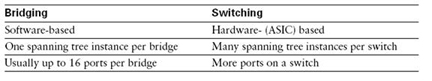 |
| |
| Frame Transmission Modes |
| |
| There are three primary frame-switching modes: |
|
|
Cut-through-The switch checks the destination address and immediately begins forwarding the frame. This can decrease latency. |
|
|
Store and forward-The switch waits to receive the entire frame before forwarding. The entire frame is read, and a cyclic redundancy check (CRC) is performed. If the CRC is bad, the frame is discarded. Latency increases as a function of frame length. |
|
|
Fragment-free (modified cut-through)-The switch reads the first 64 bytes before forwarding the frame. 64 bytes is the minimum number of bytes necessary to detect and filter out collision frames. This is the default mode for Catalyst 1900. |
|
| |
| How Switches Learn Addresses |
| |
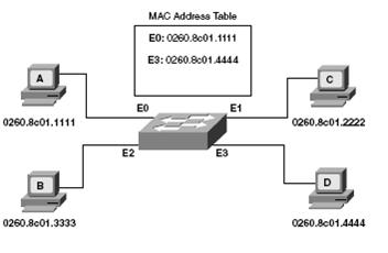
| A switch uses its bridge forwarding table (called a MAC table in Catalyst) address table when forwarding frames to devices. With an empty bridge forwarding table, the switch must flood frames to all ports other than the one it arrived on. This is the least-efficient way to transmit data. Initially, the switch MAC address table is empty. Then Station A with the MAC address sends a frame to station C. When the switch receives this frame, it does the following: |
|
|
Because the MAC table is empty, the switch must flood the frame to all other ports (except E0, the frame origin). |
|
|
The switch notes the source address of the originating device and associates it with port E0 in its MAC address table entry. Note that the table uses the source address to populate the table, not the destination address. |
|
| |
| The switch continues to learn addresses in this manner, continually updating the table. As the MAC table becomes more complete, the switching becomes more efficient, because frames are filtered to specific ports rather than being flooded out all ports. |
 |
| |
| Broadcast and Multicast Frames |
| Broadcast and multicast frames are flooded to all ports other than the originating port. Broadcast and multicast addresses never appear as a frame’s source address, so the switch does not learn these addresses. |
| |
| Basic Layer 2 Switching (Bridging) Functions Summary |
|
|
Ethernet switches are Layer 2 devices that increase a network’s available bandwidth by creating separate network segments. |
|
|
Switches have three modes of frame transmission:
Cut-through-Only the destination address is checked before the frame is forwarded.
Store and forward-The entire frame is checked before being forwarded.
Fragment-free-Only the first 64 bytes are checked before forwarding. |
|
|
Switches learn, store, and use MAC addresses to determine where a frame should be transmitted. |
|
|
A frame is forwarded to a specific port only when the destination address is known. Otherwise, it is flooded out all ports other than the one it was received on. |
|
| |
| Redundant Topology Overview |
| A redundant topology has multiple connections to switches or other devices. Redundancy ensures that a single point of failure will not cause the entire switched network to fail. However, redundancy can cause problems in a network, including broadcast storms, multiple copies of frames, and MAC address table instability. |
| |
 |
| |
| Broadcast Storms |
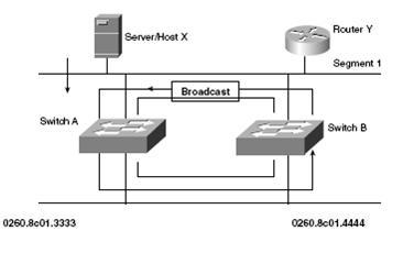
The flooding of broadcast frames can cause a broadcast storm (indefinite flooding of frames) unless there is a mechanism in place to prevent it.
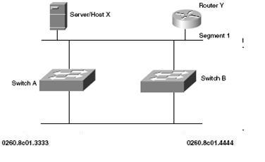
An example of a broadcast storm is shown in the figure and is described here: |
| 1 |
Host X sends a broadcast frame, which is received by switch A. |
| 2 |
Switch A checks the destination and floods it to the bottom Ethernet link, segment 2. |
| 3 |
Switch B receives the frame on the bottom port and transmits a copy to the top segment. |
| 4 |
. Because the original frame arrives at switch B through the top segment, switch B transmits the frame a second time. The frame now travels continuously in both directions. |
|
 |
| |
| Multiple Frame Transmissions |
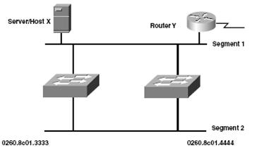
| Most protocols cannot correctly handle duplicate transmissions. Protocols that use sequence numbering assume that the sequence has recycled. Other protocols process the duplicate frame with unpredictable results. Multiple frame transmissions occur as follows: |
| 1 |
Host X sends a frame to Router Y. One copy is received over the direct Ethernet connection, segment 1. Switch A also receives a copy. |
| 2 |
Switch A checks the destination address. If the switch does not find an entry in the MAC address table for Router Y, it floods the frame on all ports except the originating port. |
| 3 |
Switch B receives the frame on segment |
| 4 |
Switch B then forwards the frame to segment 1.
Note: Router Y has now received two copies of the same frame. |
|
 |
| |
| Database Instability |
| Database instability occurs when a switch receives the same frame on different ports. The following example shows how this occurs: |
| 1 |
Host X sends a frame to Router Y. When the frame arrives at switch A and switch B, they both learn the MAC address for host X and associate it with 0. |
| 2 |
The frame is flooded out port 1 of each switch (assuming that Router Y’s address is unknown). |
| 3 |
Switch A and switch B receive the frame on port 1 and incorrectly associate host X’s MAC address with that port. |
| 4 |
This process repeats indefinitely. |
|
 |
| |
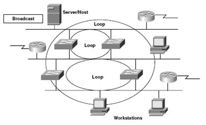
| Multiple Loops |
| Multiple loops can occur in large switched networks. When multiple loops are present, a broadcast storm clogs the network with useless traffic. Packet switching is adversely affected in this case and might not work at all. Layer 2 cannot prevent or correct broadcast storms. |
 |
| |
| Redundant Topology Summary |
|
|
A broadcast storm occurs when broadcast messages propagate endlessly throughout a switched network. |
|
|
Multiple transmissions of the same message cause errors in most protocols. |
|
|
A switch’s MAC address table becomes unstable when the switch receives the same frame on different ports. |
|
|
Layer 2 devices cannot recognize or correct looping traffic without help. |
|
| |
| Continue on to the Implementing Subnet Planning Article |
| |