In bigger networks, having a redundant design is crucial. Redundant network designs allow service continuity in case of link failure. However, the most common you will encounter will be loops. Loops are created when multiple paths exist between two network devices. IP packets have a time to live (TTL), but Ethernet frames don’t. The result is that Ethernet frames will endlessly bounce between two switches if a loop is present in your network. The same goes for broadcast messages, but their effect is bigger, meaning that you have big chances to end with a Broadcast Storm. When you encounter a loop in your network, unicast frames are also affected. Loops make unicast frames duplicate, and the destination device will receive two identical packets. All these issues can be prevented if you use STP between your network switches.
STP uses the Spanning Tree Algorithm (STA) to make decisions which switch ports to put on blocking state to prevent loops in your network.
The STP network convergence consists in three steps: elect a root bridge, elect root ports and elect designated and non-designated ports.
When you enable STP, the first step in its convergence process is to elect a switch to act as a root bridge using the Spanning Tree Algorithm. To accomplish this, all network switches participation in STP exchange BPDU frames to determine which one has the lowest bridge ID (BID). The one with the lowest BID gets elected as a root bridge by STP. The root bridge is where all spanning-tree path cost calculations begin.
Understanding the STP root bridge election process is essential for your CCNA certification exam, so we will explain it to you in greater detail.
By default, when a switch boots up, all switch ports are in blocking state for 20 seconds. During this time STP negotiates the election of the root bridge, which can take no longer than 14 seconds. At the beginning of the election process, all switches in the network assume that they are the root bridge and they start sending BPDU frames having the root ID field and the BID field the same. These frames are sent every 2 seconds. The switches then receive the frames from the other ones in the network. When they receive a frame, they compare the root ID value from that frame with its own root ID. If the one they received is lower, they update their configuration to send frames with the received root ID. When all switches found which one has the lowest ID, the election process has ended. During the normal operation of STP, switches are sending BPDU frames every 2 seconds. Each switch has a max age timer that tells the switch how much time should retain a BPDU configuration if it’s not receiving updates from the other switches. The timer by default is set to 20 seconds, meaning that if it fails to receive 10 consecutive frame from its neighbors, the switch assumes that a link to the root bridge has failed and the election of a new root bridge starts again.
To check which switch is the root bridge, use the show spanning-tree command and look for the line “This bridge is the root”.
Switch# show spanning-tree
VLAN0001
Spanning tree enabled protocol ieee
Root ID Priority 4097
Address 0004.9b78.0800
This bridge is the root
Hello Time 2 sec Max Age 20 sec Forward Delay 15 sec
Bridge ID Priority 4097 (priority 4096 sys-id-ext 1)
Address 0004.9b78.0800
Hello Time 2 sec Max Age 20 sec Forward Delay 15 sec
Aging Time 15
Interface Role Sts Cost Prio.Nbr Type
—————- —– —- ———– ——– ————————–
Fa0/1 Desg FWD 19 128.1 P2p
Fa0/1 Desg FWD 19 128.2 P2p
Sometimes, you will want to be sure a certain switch will be elected as the root bridge. You can configure a switch in two ways for this: one way is to use the spanning-tree vlan vlan-id root primary global configuration command. In case this root bridge will fail, you can specify a secondary root bridge with spanning-tree vlan vlan-id secondary. The second method is to set the priority with spanning-tree vlan vlan-id priority value global configuration command.
Switch(config)#spanning-tree vlan 1 root primary
Switch(config)#spanning-tree vlan 1 root secondary
Switch(config)#spanning-tree vlan 1 priority 24576
The spanning-tree process automatically configures 4 different port roles: root port, designated port, non-designated port and disabled port.
The root port is present only on non-root bridges and is the port with the best path to the root bridge. Only one port is allowed to be a root port.
A designated port is present in root bridges as well as on non-root bridges. In root bridges, all ports are designated ports. In non-root bridges, a designated port is the one that receives and forwards frames to the root bridge. There can be only one designated port per segment. If multiple switches exist on a segment, the switches take an election process to decide the one designated with forwarding the frames to the root bridge. Designated ports are also able to populate the MAC address table.
Non-designated ports are those ports on a switch that are in a blocking state.
Disabled ports are the ones in an administratively shut down state. Those ports are not participating in the spanning-tree process.
The port priority can be manually configured with the spanning-tree port-priority value interface configuration command. The accepted range is from 0 to 240, in increments of 16. The default priority in Cisco switches is 128.
Switch(config)#interface Fa0/1
Switch(config-if)#spanning-tree port-priority 112
To check the priority of a port, use the show spanning-tree command, as exampled above.
A port can have five possible states: blocking, listening, learning forwarding or disabled.
A port in blocking state is a non-designated port and does not participate in the frame forwarding process but it receives BPDU frames with the location and the root ID of the root bridge switch.
A listenting port is one that STP determined to participate in the frame forwarding process. This port not only is receiving BPDU frames, but is also transmitting BPDU frames to inform the adjacent switches that he’s participating in the forwarding process.
Learning ports are preparing to participate in the forwarding process and are populating the MAC address table.
Forwarding ports are forwarding frames and also are receiving and sending BPDUs.
Disabled ports are the ones in an Administratively down state. They do not participate in the STP process.
The time a switch port spends between two states depends on the following timers: Hello time, Forward delay and Maximum age. The default Hello time is 2 seconds but can be configured between 1 and 10 seconds. The forward delay is the time spent in listening and learning mode. The default is 15 seconds for each state, but can be configured between 4 and 30 seconds. The Maximum age is the amount of time a switch port stores the BPDU configuration. The default time is 20 seconds and is configurable from 5 to 40 seconds. However, Cisco is not recommending to change the default values unless you have a good reason to. These values are best for a diameter of seven. A diameter of seven is the number of switches a packet must traverse to travel from the two farthest points in the same broadcast domain and seven is the largest diameter permitted by STP. To adjust the diameter you use the global configuration command spanning-tree vlan vlan-id root primary diameter value.
Switch(config)#spanning-tree vlan 1 root primary diameter 5
The ports of a switch that are connected to a single host can take big advantage of Cisco’s proprietary PortFast technology. PortFast can be used to configure a switch port in access mode. When a port is using this technology, that switch port is switching between blocking and forwarding immediately, bypassing STP’s listening and learning states. If, for example, you will connect a PC to an STP port, and that PC is sending a DHCP request, the big port transition times will deny the PCs requests. With PortFast, the port will go instantly in forwarding state and the PC will get its IP address without any problems. To configure a switch port to use Cisco’s PortFast technology use the spanning-tree portfast interface configuration command. If for some reason you decide to switch the port back to one participating in the STP process, use no spanning-tree portfast.
Switch(config)#interface Fa0/1
Switch(config-if)#spanning-tree portfast
When a switch detects a forwarding port is going down, it considers the topology has change. When that happens, the switch sends a notification to the root bridge and the root bridge broadcasts the information in the whole network. A switch participating in the STP forwarding process is receiving configuration BPDU frames from the root bridge but never sends out a BPDU toward the root bridge unless the topology changes. When the topology changes, the switch participating to the STP forwarding process is sending a special BPDU called Topology Change Notification (TCN). The TCN is a BPDU without any information which is sent at the hello time interval. The receiving switch, called a designated bridge, acknowledges with a normal BPDU having the Topology Change Acknowledgement (TCA) bit set. The TCN then continues to travel through every switch in the network until in reaches the root bridge. Once the root bridge knows there’s a topology change in the network, it starts to send configuration BPDUs with the Topology Change (TC) bit set. The other switches are receiving TC BPDUs on both forwarding and blocking ports. The TC bit is set by the root bridge for a period of max age + forward delay seconds, 35 seconds by default.
There are many types of STP variants. Some of them are Cisco proprietary, some of them are standardized by IEEE.
Cisco’s proprietary variants are Per-VLAN Spanning Tree Protocol (PVST), Per-VLAN Spanning Tree Protocol Plus (PVST+) and Rapid PVST+.
IEEE’s standards are Rapid Spanning Tree Protocol (RSTP) and Multiple STP (MSTP).
Per-VLAN Spanning Tree Protocol (PVST) is maintaining a spanning-tree instance for each VLAN configured in the network and uses Cisco’s proprietary ISL trunking protocol. PVST can load balance traffic at Layer 2 of the OSI model without causing a loop.
Per-VLAN Spanning Tree Protocol Plus (PVST+) was developed by Cisco as a proprietary protocol to provide support for IEEEs 802.1Q trunking.
Rapid PVST+ is based on the IEEE 802.1w standard but is a Cisco proprietary protocol and has faster convergence than STP. Rapid PVST+ includes Cisco proprietary extensions such as BackboneFast, UplinkFast and PortFast.
IEEEs Rapid Spanning Tree Protocol (RSTP) was developed to provide faster STP convergence. RSTP implements Cisco proprietary extensions such as BackboneFast, UplinkFast and Portfast. Due to its faster convergence, today when you pronounce STP you think about RSTP.
Multiple STP (MSTP) allows multiple VLANs to be mapped to the same spanning-tree instance. This way you reduce the number of instances required in large networks with a big number of VLANs. MSTP can load balance data traffic because it can provide multiple data paths.
In your preparation for Cisco’s CCNA exam you must understand the concepts of PVST+, RSTP and Rapid PVST+.
PVST+ was developed by Cisco so that a network will run an STP instance for each VLAN. This feature also allows for load VLAN load balancing.
The PVST+ the bridge ID is composed of a 4 bits bridge priority, 12 bits VLAN ID (VID) and 6-byte MAC address, totaling to a 8-byte BID. Unlike in the original 802.1D standard, the bridge priority is incremented by 4096, not 1. The default priority is 32768. The second field, called Extended system ID is a 12-bit field containing the VID. Finally, the last field in the bridge ID is a 6-byte value, the MAC address.
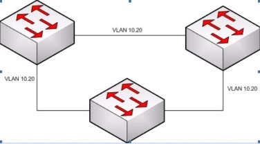
In the above diagram, VLANs 10 and 20 are enabled on all 3 routers. To avoid loops, you must enable STP. We will present you the way you will enable PVST+ in this topology. We will call the switches S1, S2 and S3. First of all you must decide what switches will be primary and secondary for each VLAN and optionally set the priority to a lower value.
S3(config)#spanning-tree mode pvst
S3(config)#spanning-tree vlan 20 root primary
S3(config)#spanning-tree vlan 10 root secondary
S3(config)#spanning-tree vlan 20 priority 4096
S1(config)#spanning-tree mode pvst
S1(config)#spanning-tree vlan 10 root primary
S1(config)#spanning-tree vlan 20 root secondary
S1(config)#spanning-tree vlan 10 priority 4096
You can then check the configuration with show spanning-tree active.
RSTP (IEEE 802.1w) is based on the original STP protocol (802.1D). Most of the parameters are the same, but the recalculation of the spanning tree is faster than from the original protocol. The network converges faster because RSTP is putting an alternate or a backup port (RSTP redefined the port types) in forwarding state immediately after it detects a change in the topology, without waiting for the network to fully converge. RSTP is the preferred protocol in the STP world because it’s backward compatible with the original 802.1D and integrates some Cisco proprietary enhancements, such as BPDUs sending Proposals and Agreements to neighbor switches. However, some other Cisco proprietary extensions are not supported, such as UplinkFast and BackboneFast. Unlike the original STP protocol, RSTP does not need timers.
RSTP uses the version 2 of BPDUs, maintaining compatibility with 802.1D, but is populating the flag byte differently. The flag byte contains the following: bits 0 and 7 are used for topology change and acknowledgment, just like in 802.1D; bits 1 and 6 are used for the Proposal Agreement process; bits 2 – 5 contains the port role and state of the port originating the BPDU.
In RSTP, an Edge port is a port that is never intended to be connected to another switch device and it comes up immediately in forwarding state. This may sound familiar from PortFast, but unlike PortFast, if an edge port receives a BPDU, it automatically becomes a normal spanning-tree port. However, the configuration of an edge port is just like in the PortFast case: with the spanning-tree portfast interface configuration command.
RSTP defines a Link Type. Link Types are used to predetermine the role a port plays in the network and stands-by for immediate transition to forwarding state if certain conditions are met. These conditions vary from edge to non-edge ports. Non-edge ports are categorized in two link types: point-to-point and shared. A point-to-point link is able used for rapid transition to forwarding state. The link type is determined automatically after RSTP determines the port roles. However, not all port types are using a link type. Root ports, alternate ports and backup ports are not using the link type parameter, or they use it only occasionally. Designated ports are the ones that are using the link type parameter most of the time.
RSTP defines 3 port states: Discarding, Learning and Forwarding. A discarding a port is a port that’s discarding the date frames. Learning ports are learning MAC addresses. Forwarding ports are the ones actively participating in the frame forwarding process.
There are 3 port roles in the RSTP process. Root ports, designated ports, and alternate ports. The Root port is the port chosen to forward the frames to the root bridge. There’s only one root port per switch. Designated ports are the ones that are able to receive frames destined for the root bridge. There can be only one designated port per segment. An alternate port offers an alternate path to the root bridge in case the root port fails. This port is in Discarding state until it switches to a designated port.
Cisco requires the CCNA exam candidate to know how to configure Rapid-PVST+. Rapid-PVST+ is the rapid STP variant used in Cisco networks. We will recall the PVST+ example and add some configurations to S1.
S1(config)#spanning-tree mode rapid-pvst
S1(config)#interface Fa0/2
S1(config-if)#spanning-tree link-type point-to-point
S1(config-if)#end
S1#clear spanning-tree detected-protocols
Now we’ve just migrated to Rapid-PVST+. Clearing the spanning-tree detected-protocols is not mandatory but is a good practice. Now let’s check the configuration with show spanning-tree vlan vlan-id and with show run.
S1# show spanning-tree
VLAN0001
Spanning tree enabled protocol rstp
Root ID Priority 4097
Address 0004.9b78.0800
This bridge is the root
Hello Time 2 sec Max Age 20 sec Forward Delay 15 sec
Bridge ID Priority 4097 (priority 4096 sys-id-ext 1)
Address 0004.9b78.0800
Hello Time 2 sec Max Age 20 sec Forward Delay 15 sec
Aging Time 15
Interface Role Sts Cost Prio.Nbr Type
—————- —– —- ———– ——– ————————–
Fa0/2 Desg LRN 19 128.2 P2p
Fa0/4 Desg LRN 19 128.4 P2p
S1#show run
………………(output omitted)…………
spanning-tree mode rapid-pvst
spanning-tree extend system-id
spanning-tree vlan 1 priority 24576
spanning-tree vlan 10 priority 4096
spanning-tree vlan 20 priority 28672
In order to avoid STP problems, you must know a few things. First of all, you must know very well the topology of your network, where your root bridge is, and what are the redundant links. If you have a good topology hierarchy, it will be easier in the future to troubleshoot STP problems if they appear. Having a large number of blocking ports can give you troubles too. If a blocking ports go accidentally to forwarding state it can affect a large part of the network. A good practice is to avoid having too many blocking ports. Another good practice is to have no more than two redundant links between to network devices. Where possible, use Layer 3 Switching. Layer 3 switching is routing at switching speed. Another problem that may occur is a network diameter that is too large. In STP, the network diameter should not be greater than 7, meaning that the longest path between two network devices must not pass more than 7 switches.
When you design your STP enabled network pay attention to these considerations. Carefully create the topology and make sure you know how a stable topology looks like, where’s the root bridge, what are the blocking ports, what are the redundant links.
We hope you found this topic covering the Spanning Tree Protocol helpful in achieving your Cisco CCNA certification. We are proud to provide not only top-notch certification articles but also real-world scenarios.