Next, we will examine how a WAN frame looks like.
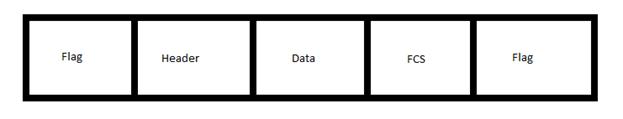
The HDLC frame structure contains the following fields, in order of precedence:
- Flag – the flag field’s bit pattern is 01111110. HDLC inserts a 0 bit every five 1s in the data field. In consecutive frames, the end flag of the first frame is used as the start flag for the next frame. The flag field is used to initiate and terminate error checking.
- Address – contains the HDLC address of the secondary station, which can be a specific address, a group address or a broadcast address. The primary address is defined as either the source or the destination address, but since WAN connections are point-to-point, there’s no need to specify that.
- Control – uses three different formats, depending on the type of HDLC frame used:
- Information (I) frames – used to carry upper layer information and some control information. I-frames are sending and receiving sequence numbers, used to refer to the number of the frame to be sent or received next. I-frames also contain the poll final (P/F) bit. A P/F bit is used by the primary station to tell the secondary weather it requires an immediate response. The secondary station uses the P/F bit to tell the primary one if the current frame is the last in its current response.
- Supervisory (S) frames – are providing control information. S-frames can request and suspend transmission, report on status and acknowledge receipt of I-frames.
- Unnumbered (U) frames – mainly used for control purposes, can be used to initialize secondary stations. They are not sequenced and have the control field of 1 or 2 bytes. Some U-frames have the information while other do not.
- Protocol – the protocol field appears only in Cisco’s proprietary HDLC (cHDLC) and is used to specify the Network layer protocol type encapsulated in the frame, in hexadecimal format (e.g. 0x08000 for IP).
- Data – the data field contains path information unit (PIU) or exchange identification (XID).
- Frame check sequence (FCS) – is usually a cyclic redundancy check (CRC). If the receiving device finds that the CRC calculation of the received frame differs from the one in the FCS field, it assumes there’s an error and notifies the other device to resent the frame.
- Flag – the ending flag delimiter.
The default encapsulation type for synchronous serial interfaces on a Cisco device is HDLC. If the default configuration has been changed, you can still modify the encapsulation type of a serial interface with encapsulation hdlc interface configuration command.
Router(config)#interface serial 0/0/0
Router(config-if)#encapsulation hdlc
To verify a serial interface is up and the correct encapsulation type is configured, use the show interfaces serial command.Router# show interfaces serial
Serial 0 is up, line protocol is up
Hardware is MCI Serial
Internet address is 150.136.190.203, subnet mask is 255.255.255.0
MTU 1500 bytes, BW 1544 Kbit, DLY 20000 usec, rely 255/255, load 1/255
Encapsulation HDLC, loopback not set, keepalive set (10 sec)
Last input 0:00:07, output 0:00:00, output hang never
Output queue 0/40, 0 drops; input queue 0/75, 0 drops
Five minute input rate 0 bits/sec, 0 packets/sec
Five minute output rate 0 bits/sec, 0 packets/sec
16263 packets input, 1347238 bytes, 0 no buffer
Received 13983 broadcasts, 0 runts, 0 giants
2 input errors, 0 CRC, 0 frame, 0 overrun, 0 ignored, 2 abort
1 carrier transitions
22146 packets output, 2383680 bytes, 0 underruns
0 output errors, 0 collisions, 2 interface resets, 0 restarts
If your serial interface is not working, the first thing to do is to pay attention at your interface status. If you see any of the following statuses instead of Serial X is up, line protocol is up, you have a connectivity or a configuration problem:
- Serial X is down, line protocol is down
- Serial X is up, line protocol is down
- Serial X is up, line protocol is up (looped)
- Serial X is up, line protocol is down (disabled)
- Serial X is administratively down, line protocol is down
Another important troubleshooting command is show controllers. With this command, you can find out the state of the interface channels and weather it has a cable attached. If the electrical interface output is UNKNOWN instead of V.35, EIA/TIA-449 or any other type of electrical interface type, you probably have an improperly connected cable.
Router#show controllers serial 0/0/0
Interface Serial0/0/0
Hardware is GT96K
DCE V.35, clock rate 64000
…………((output omitted))…………
Serial interfaces can also be configured to use PPP encapsulation with encapsulation ppp interface configuration command. The troubleshooting steps are the same like in the HDLC case, because you are troubleshooting the serial interface, not the encapsulation type.
Router(config)#interface serial 0/0/0
Router(config-if)#encapsulation ppp
The CCNA exam requires a candidate to know the Frame Relay encapsulation types also.
When Frame Relay gets a packet from a network layer protocol, it wraps it with an address field containing the DLCI and a checksum. Just like with HDLC, the Flag fields at the beginning and the end of the frame are added. The Flag fields are represented by the hexadecimal number 7E or by the number 01111110. After the packet is encapsulated, Frame Relay is passing the frame to the Physical layer.
The CPE routers are in charge of encapsulating Layer 3 packets in a Frame Relay header and trailer before sending them to VCs. Headers and trailers are defined by the Link Access Procedure for Frame Relay (LAPF) Bearer Service specification, ITU Q.922-A.
A Frame Relay header contains:
- DLCI – is a 10-bit identifier representing the virtual connection between the DTE device and the switch. Each virtual connection has its unique DLCI. DLCIs have local significance only, meaning that the device from the other end can use a different DLCI for the same virtual connection.
- Extended Address (EA) – this is used to allow longer DLCIs in the future. The last octet in the DLCI denotes where the EA begins. The value in the EA field is usually 1.
- C/R – this field is not usually used by Frame Relay.
- Congestion Control – contains 3 bits used to control the congestion notification mechanism in Frame Relay. The FECN, BECN and DE bits are the last three bits.
Before the ending Flag field, just like in the HDLC case, there’s a FCS field used for error control.
To configure a serial interface to use frame relay encapsulation, use the encapsulation frame-relay interface configuration command.
Router(config)#interface serial 0/0/0
Router(config-if)#encapsulation frame-relay
If the encapsulation is correctly configured, when you use the show interfaces serial 0/0/0 command, you should see encapsulation set to Frame Relay.
Router#show interfaces serial 0/0/0
Serial0/0/0 is up, line protocol is up
Hardware is GT96K Serial
Internet address is 10.1.1.1/24
MTU 1500 bytes, BW 64 Kbit, DLY 2000 usec,
reliability 255/255, txload 1/255, rxload 1/255
Encapsulation FRAME-RELAY, loopback not set
Keepalive set (10 sec)
We have covered in this CCNA topic the WAN encapsulation types as requested in the CCNA certification exam. After you’ll pass the CCNA exam, you may want to go for a higher-level certification, such as CCNP. If you will continue your networking education by training for and passing the higher-level exams, you will find more exciting and challenging WAN concepts and protocols.