In preparation of our CCNA exam, we want to make sure we cover the various concepts that we could see on our Cisco CCNA exam. So to assist you, below we will discuss X-25
X.25: ITU-T Protocol for WAN Communications
X.25, an ITU-T protocol for WAN communications, is a packet switched data network protocol which defines the exchange of data as well as control information between a user device, called Data Terminal Equipment (DTE) and a network node, called Data Circuit Terminating Equipment (DCE).
X.25 is designed to operate effectively regardless of the type of systems connected to the network. X.25 is typically used in the packet-switched networks (PSNs) of common carriers, such as the telephone companies. Subscribers are charged based on their use of the network. X.25 utilizes a Connection-Oriented service which insures that packets are transmitted in order.
X.25 sessions are established when one DTE device contacts another to request a communication session. The DTE device that receives the request can either accept or refuse the connection. If the request is accepted, the two systems begin full-duplex information transfer. Either DTE device can terminate the connection. After the session is terminated, any further communication requires the establishment of a new session. X.25 uses virtual circuits for packets communications. Both switched and permanent virtual circuits are used.
X.75 is the signaling protocol for X.25, which defines the signaling system between two PDNs. X.75 is essentially an Network to Network Interface (NNI).
X.25 protocol suite comes with three levels based on the first three layers of the OSI seven layers architecture.
The Physical Level: describes the interface with the physical environment. There are three protocols in this group: 1) X.21 interface operates over eight interchange circuits; 2) X.21bis defines the analogue interface to allow access to the digital circuit switched network using an analogue circuit; 3) V.24 provides procedures which enable the DTE to operate over a leased analogue circuit connecting it to a packet switching node or concentrator.
The Link Level: responsible for the reliable communication between the DTE and the DCE. There are four protocols in this group: 1) LAPB, derived from HDLC and the most commonly used, enables to form a logical link connection besides all the other characteristics of HDLC; 2) Link Access Protocol (LAP) is an earlier version of LAPB and is seldom used today; 3) LAPD, derived from LAPB and used for ISDN, enables data transmission between DTEs through D channel, especially between a DTE and an ISDN node; 4) Logical Link Control (LLC), an IEEE 802 LAN protocol, enables X.25 packets to be transmitted through a LAN channel.
The Packet Layer Protocol (PLP): describes the data transfer protocol in the packet switched network at the network layer (layer 3). PLP manages packet exchanges between DTE devices across virtual circuits. PLPs also can run over Logical Link Control 2 implementations on LANs as well as over ISDN interfaces running LAPD. The PLP operates in five distinct modes: call setup, data transfer, idle, call clearing, and restarting.
- Call setup mode is used to establish SVCs between DTE devices.
- Data transfer mode is used for transferring data between two DTE devices across a virtual circuit.
- Idle mode is used when a virtual circuit is established but data transfer is not occurring.
- Call clearing mode is used to end communication sessions between DTE devices and to terminate SVCs.
- Restarting mode is used to synchronize transmission between a DTE device and a locally connected DCE device.
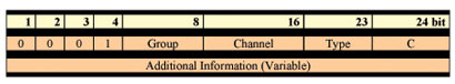
Protocol Structure – X.25: ITU-T Protocol for WAN CommunicationsX.25 PLP has many control messages. The control packet as well as all X.25 packets begins with a 3- byte header. Bytes 1,2 contain the Group and the Channel fields that together form a 12 bit virtual circuit number. The additional information for each message is different.
1. Control Packet
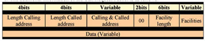
2. The additional information of the Call Request Packet is as follows:
Other Control Packets are:
- The CALL ACCEPTED packet is sent by the callee DTE if it accepts the call.
- The CLEAR REQUEST is sent due to various reasons,the fourth byte of the packet tells why the connection is being cleared. It is acknowledged by a CLEAR REQUEST CONFIRMATION packet.
- The INTERRUPT packet allows a short (32 bytes) signal to be sent out of sequence. It is acknowledged by INTERRUPT CONFIRMATION packet.
- The RECEIVE READY (RR) packet is used to send separate acknowledgments where there is no reverse traffic. The ppp field (three first bits of the type field) tells which packet is expected next.
- The RECEIVE NOT READY (RNR) packet allows a DTE to tell the other side to stop sending packets to it for a while.
- The REJECT packet allows a DTE to request retransmission of a series of packets. The ppp field gives the first sequence number desired.
- The RESET and RESTART packets are used to recover from varying degrees of trouble. Both are acknowledged by RESET CONFIRMATION and RESTART CONFIRMATION respectively.
- The DIAGNOSTIC packet is also provided, to allow the network to inform the user of problems.
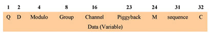
3. The format of data packet is as follows:
I hope you found this article to be of use and it helps you prepare for your Cisco CCNA certification. Achieving your CCNA certification is much more than just memorizing Cisco exam material. It is having the real world knowledge to configure your Cisco equipment and be able to methodically troubleshoot Cisco issues. So I encourage you to continue in your studies for your CCNA exam certification.