In preparation of our CCNA exam, we want to make sure we cover the various concepts that we could see on our Cisco CCNA exam. So to assist you, below we will discuss Access Control Lists.
You can configure network security by using ACLs by either using the Cluster Management Suite (CMS) or through the command-line interface (CLI).
You can also use the security wizard to filter inbound traffic on the Catalyst 2950 switches. Filtering can be based on network addresses or TCP/UDP applications. You can choose whether to drop or forward packets that meet the filtering criteria. To use this wizard, you must know how the network is designed and how interfaces are used on the filtering device.
Understanding ACLs
Packet filtering can limit network traffic and restrict network use by certain users or devices. ACLs can filter traffic as it passes through a switch and permit or deny packets from crossing specified interfaces. An ACL is a sequential collection of permit and deny conditions that apply to packets. When a packet is received on an interface, the switch compares the fields in the packet against any applied ACLs to verify that the packet has the required permissions to be forwarded, based on the criteria specified in the access lists. The switch tests the packet against the conditions in an access list one by one. The first match determines whether the switch accepts or rejects the packet. Because the switch stops testing conditions after the first match, the order of conditions in the list is critical. If no conditions match, the switch rejects the packet. If there are no restrictions, the switch forwards the packet; otherwise, the switch drops the packet.
You configure access lists on a Layer 2 switch to provide basic security for your network. If you do not configure ACLs, all packets passing through the switch could be allowed onto all parts of the network. You can use ACLs to control which hosts can access different parts of a network or to decide which types of traffic are forwarded or blocked at switch interfaces. For example, you can allow e-mail traffic to be forwarded but not Telnet traffic. ACLs can be configured to block inbound traffic.
An ACL contains an ordered list of access control entries (ACEs). Each ACE specifies permit or deny and a set of conditions the packet must satisfy in order to match the ACE. The meaning of permit or deny depends on the context in which the ACL is used.
The switch supports these types of ACLs:
- IP ACLs filter IP traffic, including TCP and User Datagram Protocol (UDP).
- Ethernet ACLs filter Layer 2 traffic.
ACLs
You can apply ACLs on management VLANs, and on physical Layer 2 interfaces. ACLs are applied on interfaces for inbound directions.
- Standard IP access lists use source addresses for matching operations.
- Extended IP access lists use source and destination addresses and optional protocol type information for matching operations.
- MAC extended access list use source and destination mac addresses and optional protocol type information for matching operations.
The switch examines access lists associated with features configured on a given interface and a direction. As packets enter the switch on an interface, ACLs associated with all inbound features configured on that interface are examined.
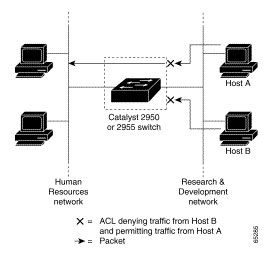
ACLs permit or deny packet forwarding based on how the packet matches the entries in the ACL. For example, you can use ACLs to allow one host to access a part of a network, but to prevent another host from accessing the same part. In Figure 12-1, ACLs applied at the switch input allow Host A to access the Human Resources network, but prevent Host B from accessing the same network.
Figure 12-1 Using ACLs to Control Traffic to a Network
Handling Fragmented and Unfragmented Traffic
IP packets can be fragmented as they cross the network. When this happens, only the fragment containing the beginning of the packet contains the Layer 4 information, such as TCP or UDP port numbers, ICMP type and code, and so on. All other fragments are missing this information. Some ACEs do not check Layer 4 information and therefore can be applied to all packet fragments. ACEs that do test Layer 4 information cannot be applied in the standard manner to most of the fragments in a fragmented IP packet. When the fragment contains no Layer 4 information and the ACE tests some Layer 4 information, the matching rules are modified:
- Permit ACEs that check the Layer 3 information in the fragment (including protocol type, such as TCP, UDP, and so on) are considered to match the fragment regardless of what the missing Layer 4 information might have been.
- Deny ACEs that check Layer 4 information never match a fragment unless the fragment contains Layer 4 information.
Consider access list 102, configured with these commands, applied to three fragmented packets:
Switch (config)# access-list 102 permit tcp any host 10.1.1.1 eq smtp
Switch (config)# access-list 102 deny tcp any host 10.1.1.2 eq telnet
Switch (config)# access-list 102 deny tcp any any
Note In the first and second ACEs in the examples, the eq keyword after the destination address means to test for the TCP-destination-port well-known numbers equaling Simple Mail Transfer Protocol (SMTP) and Telnet, respectively.
- Packet A is a TCP packet from host 10.2.2.2, port 65000, going to host 10.1.1.1 on the SMTP port. If this packet is fragmented, the first fragment matches the first ACE (a permit), as if it were a complete packet because all Layer 4 information is present. The remaining fragments also match the first ACE, even though they do not contain the SMTP port information because the first ACE only checks Layer 3 information when applied to fragments. (The information in this example is that the packet is TCP and that the destination is 10.1.1.1.)
- Packet B is from host 10.2.2.2, port 65001, going to host 10.1.1.2 on the Telnet port. If this packet is fragmented, the first fragment matches the second ACE (a deny) because all Layer 3 and Layer 4 information is present. The remaining fragments in the packet do not match the second ACE because they are missing Layer 4 information.
- Because the first fragment was denied, host 10.1.1.2 cannot reassemble a complete packet, so packet B is effectively denied. However, the later fragments that are permitted will consume bandwidth on the network and resources of host 10.1.1.2 as it tries to reassemble the packet.
- Fragmented packet C is from host 10.2.2.2, port 65001, going to host 10.1.1.3, port ftp. If this packet is fragmented, the first fragment matches the third ACE (a deny). All other fragments also match the third ACE because that ACE does not check any Layer 4 information and because Layer 3 information in all fragments shows that they are being sent to host 10.1.1.3, and the earlier permit ACEs were checking different hosts.
Understanding Access Control Parameters
Before configuring ACLs on the Catalyst 2950 switches, you must have a thorough understanding of the Access Control Parameters (ACPs). ACPs are referred to as masks in the switch CLI commands, output, and CMS. Each ACE has a mask and a rule. The Classification Field or mask is the field of interest on which you want to perform an action. The specific values associated with a given mask are called rules. Packets can be classified on these Layer 2, Layer 3, and Layer 4 fields.
- Layer 2 fields:
o Source MAC address (Specify all 48 bits.)
o Destination MAC address (Specify all 48 bits.)
o Ethertype (16-bit ethertype field)You can use any combination or all of these fields simultaneously to define a flow.
- Layer 3 fields:
o IP source address (Specify all 32 IP source address bits to define the flow, or specify an user- defined subnet. There are no restrictions on the IP subnet to be specified.)
o IP destination address (Specify all 32 IP destination address bits to define the flow, or specify an user- defined subnet. There are no restrictions on the IP subnet to be specified.)You can use any combination or all of these fields simultaneously to define a flow.
- Layer 4 fields:
o TCP (You can specify a TCP source, destination port number, or both at the same time.)
o UDP (You can specify a UDP source, destination port number, or both at the same time.)
Note A mask can be a combination of either multiple Layer 3 and Layer 4 fields or of multiple Layer 2 fields. Layer 2 fields cannot be combined with Layer 3 or Layer 4 fields.
There are two types of masks:
- User-defined mask—masks that are defined by the user.
- System-defined mask—these masks can be configured on any interface:
Switch (config-ext-nacl)# permit tcp any any
Switch (config-ext-nacl)# deny tcp any any
Switch (config-ext-nacl)# permit udp any any
Switch (config-ext-nacl)# deny udp any any
Switch (config-ext-nacl)# permit ip any any
Switch (config-ext-nacl)# deny ip any any
Switch (config-ext-nacl)# deny any any
Switch (config-ext-nacl)# permit any any
Note In an IP extended ACL (both named and numbered), a Layer 4 system-defined mask cannot precede a Layer 3 user-defined mask. For example, a Layer 4 systemdefined mask such as permit tcp any any or deny udp any any cannot precede a Layer 3 user-defined mask such as permit ip 10.1.1.1 any. If you configure this combination, the ACL is not configured. All other combinations of system-defined and user-defined masks are allowed in security ACLs.
The Catalyst 2950 switch ACL configuration is consistent with other Cisco Catalyst switches. However, there are significant restrictions as well as differences for ACL configurations on the Catalyst 2950 switches.
Guidelines for Configuring ACLs on the Catalyst 2950 Switches
These configuration guidelines apply to ACL filters:
- Only one ACL can be attached to an interface. For more information, refer to the ip access-group interface command in the Catalyst 2950 Desktop Switch Command Reference.
- All ACEs in an ACL must have the same user-defined mask. However, ACEs can have different rules that use the same mask. On a given interface, only one type of user-defined mask is allowed, but you can apply any number of system-defined masks. This example shows the same mask in an ACL:
Switch (config)#ip access-list extended acl2
Switch (config-ext-nacl)# permit tcp 10.1.1.1 0.0.0.0 any eq 80
Switch (config-ext-nacl)# permit tcp 20.1.1.1 0.0.0.0 any eq 23
In this example, the first ACE permits all the TCP packets coming from the host 10.1.1.1 with a destination TCP port number of 80. The second ACE permits all TCP packets coming from the host 20.1.1.1 with a destination TCP port number of 23. Both the ACEs use the same mask; therefore, a Catalyst 2950 switch supports this ACL.
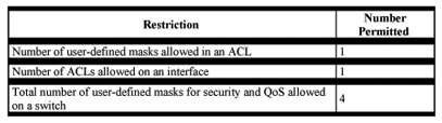
- Only four user-defined masks can be defined for the entire system. These can be used for either security or quality of service (QoS) but cannot be shared by QoS and security. You can configure as many ACLs as you require. However, a system error message appears if ACLs with more than four different masks are applied to interfaces.
Table 12-1 lists a summary of the ACL restrictions on Catalyst 2950 switches.
Table 12-1 Summary of ACL Restrictions
Configuring ACLs
Configuring ACLs on Layer 2 or Layer 3 management VLAN interfaces is the same as configuring ACLs on Cisco routers. The process is briefly described here.
Unsupported Features
The Catalyst 2950 switch does not support these IOS router ACL-related features:
- Non-IP protocol ACLs (see Table 12-2).
- Bridge-group ACLs.
- IP accounting.
- No ACL support on the outbound direction.
- Inbound and outbound rate limiting (except with QoS ACLs).
- IP packets with a header length of less than five are not be access-controlled.
- Reflexive ACLs.
- Dynamic ACLs (except for certain specialized dynamic ACLs used by the switch clustering feature.
- ICMP-based filtering.
- IGMP-based filtering.
Creating Standard and Extended IP ACLs
This section describes how to create switch IP ACLs. An ACL is a sequential collection of permit and deny conditions. The switch tests packets against the conditions in an access list one by one. The first match determines whether the switch accepts or rejects the packet. Because the switch stops testing conditions after the first match, the order of the conditions is critical. If no conditions match, the switch denies the packet.
Use these steps to use ACLs:
Step 1 Create an ACL by specifying an access list number or name and access conditions.
Step 2 Apply the ACL to interfaces or terminal lines.
The software supports these styles of ACLs or IP access lists:
- Standard IP access lists use source addresses for matching operations.
- Extended IP access lists use source and destination addresses for matching operations and optional protocol-type information for finer granularity of control.
- MAC extended access list use source and destination MAC addresses and optional protocol type information for matching operations.
The next sections describe access lists and the steps for using them.
ACL Numbers
The number you use to denote your ACL shows the type of access list that you are creating. Table 12-2 lists the access list number and corresponding type and shows whether or not they are supported by the switch. The Catalyst 2950 switch supports IP standard and IP extended access lists, numbers 1 to 199 and 1300 to 2699.
Table 12-2 Access List Numbers
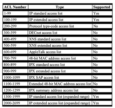
Note In addition to numbered standard and extended ACLs, you can also create standard and extended named IP ACLs by using the supported numbers. That is, the name of a standard IP ACL can be 1 to 99; the name of an extended IP ACL can be 100 to 199. The advantage of using named ACLs instead of numbered lists is that you can delete individual entries from a named list.
Creating a Numbered Standard ACL
Beginning in privileged EXEC mode, follow these steps to create a numbered standard ACL:
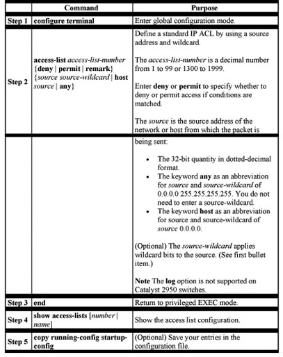
Use the no access-list access-list-number global configuration command to delete the entire ACL. You cannot delete individual ACEs from numbered access lists.
Note When creating an ACL, remember that, by default, the end of the ACL contains an implicit deny statement for all packets that it did not find a match for before reaching the end. With standard access lists, if you omit the ask from an associated IP host address ACL specification, 0.0.0.0 is assumed to be the mask.
This example shows how to create a standard ACL to deny access to IP host 171.69.198.102, permit access to any others, and display the results.
Switch (config)# access-list 2 deny host 171.69.198.102
Switch (config)# access-list 2 permit any
Switch(config)# end
Switch# show access-lists
Standard IP access list 2
deny 171.69.198.102
permit any
Creating a Numbered Extended ACL
Although standard ACLs use only source addresses for matching, you can use an extended ACL source and destination addresses for matching operations and optional protocol type information for finer granularity of control. Some protocols also have specific parameters and keywords that apply to that protocol.
These IP protocols are supported (protocol keywords are in parentheses in bold): Internet Protocol (ip), Transmission Control Protocol (tcp), or User Datagram Protocol (udp).
Supported parameters can be grouped into these categories:
- TCP
- UDP
Table 12-3 lists the possible filtering parameters for ACEs for each protocol type.
Table 12-3 Filtering Parameter ACEs Supported by Different IP Protocols
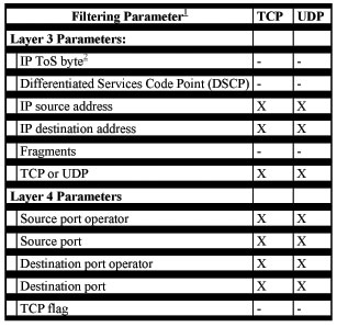
For more details on the specific keywords relative to each protocol, refer to the Cisco IP and IP Routing Command Reference for IOS Release 12.1.
Note The Catalyst 2950 switch does not support dynamic or reflexive access lists. It also does not support filtering based on the minimize-monetary-cost type of service (TOS) bit.
When creating ACEs in numbered extended access lists, remember that after you create the list, any additions are placed at the end of the list. You cannot reorder the list or selectively add or remove ACEs from a numbered list.
Beginning in privileged EXEC mode, follow these steps to create an extended ACL:
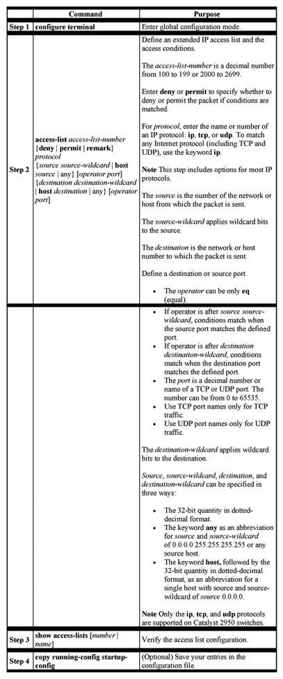
Use the no access-list access-list-number global configuration command to delete the entire access list. You cannot delete individual ACEs from numbered access lists.
This example shows how to create and display an extended access list to deny Telnet access from any host in network 171.69.198.0 to any host in network 172.20.52.0 and permit any others. (The eq keyword after the destination address means to test for the TCP destination port number equaling Telnet.)
Switch(config)# accesslist
102 deny tcp 171.69.198.0 0.0.0.255 172.20.52.0 0.0.0.255 eq telnet
Switch(config)# access-list 102 permit tcp any any
Switch(config)# end
Switch# show access-lists
Extended IP access list 102
deny tcp 171.69.198.0 0.0.0.255 172.20.52.0 0.0.0.255 eq telnet
permit tcp any any
After an ACL is created, any additions (possibly entered from the terminal) are placed at the end of the list. You can add ACEs to an ACL, but deleting any ACE deletes the entire ACL.
Note When creating an ACL, remember that, by default, the end of the access list contains an implicit deny statement for all packets if it did not find a match before reaching the end.
After creating an ACL, you must apply it to a line or interface.
Creating Named Standard and Extended ACLs
You can identify IP ACLs with an alphanumeric string (a name) rather than a number. You can use named ACLs to configure more IP access lists on a switch than if you use numbered access lists. If you identify your access list with a name rather than a number, the mode and command syntax are slightly different. However, not all commands that use IP access lists accept a named ACL.
Note The name you give to a standard ACL or extended ACL can also be a number in the supported range of access list numbers. That is, the name of a standard IP ACL can be 1 to 99; the name of an extended IP ACL can be 100 to 199. The advantage of using named ACLs instead of numbered lists is that you can delete individual entries from a named list.
Consider these guidelines and limitations before configuring named ACLs:
- A standard ACL and an extended ACL cannot have the same name.
- Numbered ACLs are also available, as described in the “Creating Standard and Extended IP ACLs” section.
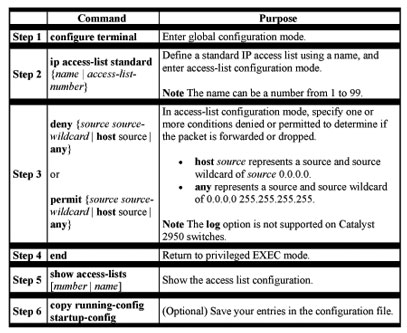
Beginning in privileged EXEC mode, follow these steps to create a standard access list using names:
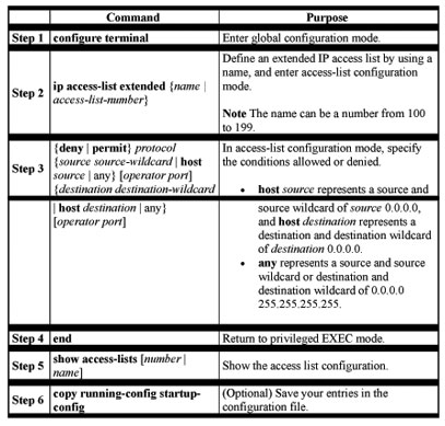
Beginning in privileged EXEC mode, follow these steps to create an extended ACL using names:
When making the standard and extended ACL, remember that, by default, the end of the ACL contains an implicit deny statement for everything if it did not find a match before reaching the end. For standard ACLs, if you omit the mask from an associated IP host address access list specification, 0.0.0.0 is assumed to be the mask.
After you create an ACL, any additions are placed at the end of the list. You cannot selectively add ACEs to a specific ACL. However, you can use no permit and no deny commands to remove ACEs from a named ACL. This example shows how you can delete individual ACEs from a named ACL:
Switch(config)# ip access-list extended border-list
Switch(config-ext-nacl)# no permit ip host 10.1.1.3 any
Being able to selectively remove lines from a named ACL is one reason you might use named ACLs instead of numbered ACLs.
After creating an ACL, you must apply it to a line or interface.
Including Comments About Entries in ACLs
You can use the remark command to include comments (remarks) about entries in any IP standard or extended ACL. The remarks make the ACL easier for you to understand and scan. Each remark line is limited to 100 characters.
The remark can go before or after a permit or deny statement. You should be consistent about where you put the remark so that it is clear which remark describes which permit or deny statement. For example, it would be confusing to have some remarks before the associated permit or deny statements and some remarks after the associated statements. For IP numbered standard or extended ACLs, use the access-list access-list number remark remark global configuration command to include a comment about an access list.
To remove the remark, use the no form of this command.
In this example, the workstation belonging to Jones is allowed access, and the workstation belonging to Smith is not allowed access:
Switch(config)# access-list 1 remark Permit only Jones workstation through
Switch(config)# access-list 1 permit 171.69.2.88
Switch(config)# access-list 1 remark Do not allow Smith workstation through
Switch(config)# access-list 1 deny 171.69.3.13
For an entry in a named IP ACL, use the remark access-list global configuration command. To remove the remark, use the no form of this command.
In this example, the Jones subnet is not allowed to use outbound Telnet:
Switch(config)# ip access-list extended telnetting
Switch(config-ext-nacl)# remark Do not allow Jones subnet to telnet out
Switch(config-ext-nacl)# deny tcp host 171.69.2.88 any eq telnet
Applying the ACL to an Interface or Terminal Line
After you create an ACL, you can apply it to one or more interfaces or terminal lines. ACLs can be applied on inbound interfaces. This section describes how to accomplish this task for both terminal lines and network interfaces. Note these guidelines:
- When controlling access to a line, you must use a number. Numbered ACLs and MAC extended ACLs can be applied to lines.
- When controlling access to an interface, you can use a name or number.
- Set identical restrictions on all the virtual terminal lines because a user can attempt to connect to any of them.
- If you apply an ACL to a Layer-3 interface, the ACL only filters packets that are intended for the CPU, such as SNMP, Telnet or Web traffic.
Beginning in privileged EXEC mode, follow these steps to restrict incoming connections between a virtual terminal line and the addresses in an ACL:
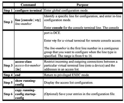
Beginning in privileged EXEC mode, follow these steps to control access to a Layer 2 or Layer 3 interface:
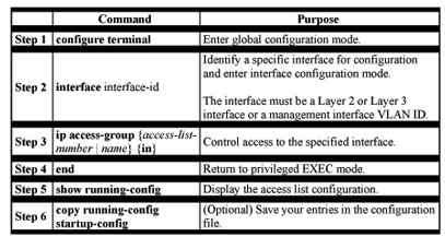
This example shows how to apply access list 2 on Gigabit Ethernet interface 0/3 to filter packets entering the interface:
Switch(config)# interface gigabitethernet0/3
Router(config-if)# ip access-group 2 in
Note The ip access-group interface configuration command is only valid when applied to an management interface, a Layer 2 interface, or a Layer 3 interface. If applied to a Layer 3 interface, the interface must have been configured with an IP address. ACLs cannot be applied to interface port-channels.
For inbound ACLs, after receiving a packet, the switch checks the packet against the ACL. If the ACL permits the packet, the switch continues to process the packet. If the ACL rejects the packet, the switch discards the packet.
When you apply an undefined ACL to an interface, the switch acts as if the ACL has not been applied to the interface and permits all packets. Remember this behavior if you use undefined ACLs for network security.
Displaying ACLs
You can display existing ACLs by using show commands.
Beginning in privileged EXEC mode, follow these steps to display access lists:
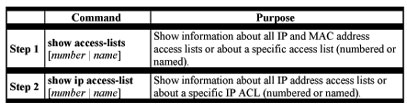
This example displays all standard and extended ACLs:
Switch# show access-lists
Standard IP access list 1
permit 172.20.10.10
Standard IP ACL 10
permit 12.12.12.12
Standard IP access list 12
deny 1.3.3.2
Standard IP access list 32
permit 172.20.20.20
Standard IP access list 34
permit 10.24.35.56
permit 23.45.56.34
Extended IP access list 120
Extended MAC access list mac1
This example displays only IP standard and extended ACLs.
Switch# show ip access-lists
Standard IP access list 1
permit 172.20.10.10
Standard IP access list 10
permit 12.12.12.12
Standard IP access list 12
deny 1.3.3.2
Standard IP access list 32
permit 172.20.20.20
Standard IP access list 34
permit 10.24.35.56
permit 23.45.56.34
Extended IP access list 120
Displaying Access Groups
You use the ip access-group interface configuration command to apply ACLs to a Layer 3 interface. When IP is enabled on an interface, you can use the show ip interface interface-id privileged EXEC command to view the input and output access lists on the interface, as well as other interface characteristics. If IP is not enabled on the interface, the access lists are not shown.
This example shows how to view all access groups configured for VLAN 1 and for Gigabit Ethernet interface 0/2:
Switch# show ip interface vlan 1
GigabitEthernet0/2 is up, line protocol is down
Internet address is 10.20.30.1/16
Broadcast address is 255.255.255.255
Address determined by setup command
MTU is 1500 bytes
Helper address is not set
Directed broadcast forwarding is disabled
Outgoing access list is permit Any
Inbound access list is 13
< information truncated>
Switch# show ip interface f0/9
FastEthernet0/9 is down, line protocol is down
Inbound access list is ip1
The only way to ensure that you can view all configured access groups under all circumstances is to use the show running-config privileged EXEC command. To display the ACL configuration of a single interface, use the show running-config interface interface-id command.
This example shows how to display the ACL configuration of Gigabit Ethernet interface 0/1:
Switch# show running-config interface gigabitethernet0/1
Building configuration…
Current configuration :112 bytes
!
interface GigabitEthernet0/1
ip access-group 11 in
snmp trap link-status
no cdp enable
end!
Examples for Compiling ACLs
For detailed information about compiling ACLs, refer to the Security Configuration Guide and the “IP Services” chapter of the Cisco IOS IP and IP Routing Configuration Guide for IOS Release 12.1.
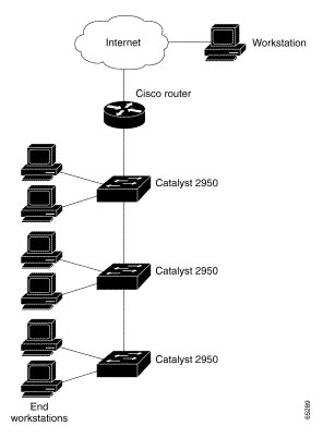
Figure 12-2 shows a small networked office with a stack of Catalyst 2950 switches that are connected to a Cisco router. A host is connected to the network through the Internet using a WAN link.
Use switch ACLs to do these:
- Create a standard ACL, and filter traffic from a specific Internet host with an address 172.20.128.64.
- Create an extended ACL, and filter traffic to deny HTTP access to all Internet hosts but allow all other types of access.
Figure 12-2 Using Switch ACLs to Control Traffic
This example uses a standard ACL to allow access to a specific Internet host with the address 172.20.128.64.
Switch(config)# access-list 6 permit 172.20.128.64 0.0.0.0
Switch(config)# end
Switch(config)# interface gigabitethernet0/1
Switch(config-if)# ip access-group 6 in
This example uses an extended ACL to deny traffic from port 80 (HTTP). It permits all other types of traffic.
Switch(config)# access-list 106 deny tcp any any eq 80
Switch(config)# access-list 106 permit ip any any
Switch(config)# interface gigabitethernet0/2
Switch(config-if)# ip access-group 106 in
Numbered ACL Examples
This example shows that the switch accepts addresses on network 36.0.0.0 subnets and denies all packets coming from 56.0.0.0 subnets. The ACL is then applied to packets entering Gigabit Ethernet interface 0/1.
Switch(config)# access-list 2 permit 36.0.0.0 0.255.255.255
Switch(config)# access-list 2 deny 56.0.0.0 0.255.255.255
Switch(config)# interface gigabitethernet0/1
Switch(config-if)# ip access-group 2 in
Extended ACL Examples
In this example of using an extended ACL, you have a network connected to the Internet, and you want any host on the network to be able to form TCP Telnet and SMTP connections to any host on the Internet.
Switch(config)# access-list 102 permit tcp any 128.88.0.0 0.0.255.255 eq 23
Switch(config)# access-list 102 permit tcp any 128.88.0.0 0.0.255.255 eq 25
Switch(config)# interface gigabitethernet0/1
Switch(config-if)# ip access-group 102 in
SMTP uses TCP port 25 on one end of the connection and a random port number on the other end. The same port numbers are used throughout the life of the connection. Mail packets coming in from the Internet have a destination port of 25. Because the secure system behind the switch always accepts mail connections on port 25, the incoming services are controlled.
Named ACL Example
The Marketing_group ACL allows any TCP Telnet traffic to the destination address and wildcard 171.69.0.0 0.0.255.255 and denies any other TCP traffic. It permits any other IP traffic.
Switch(config)# ip access-list extended marketing_group
Switch(config-ext-nacl)# permit tcp any 171.69.0.0 0.0.255.255 eq telnet
Switch(config-ext-nacl)# deny tcp any any
Switch(config-ext-nacl)# permit ip any any
The ACLs are applied to permit Gigabit Ethernet port 0/1, which is configured as a Layer 2 port, with the Marketing_group ACL applied to incoming traffic.
Switch(config)# interface gigabitethernet0/1
Switch(config-if)# ip access-group marketing_group in
…
Commented IP ACL Entry Examples
In this example of a numbered ACL, the workstation belonging to Jones is allowed access, and the workstation belonging to Smith is not allowed access:
Switch(config)# access-list 1 remark Permit only Jones workstation through
Switch(config)# access-list 1 permit 171.69.2.88
Switch(config)# access-list 1 remark Do not allow Smith workstation through
Switch(config)# access-list 1 deny 171.69.3.13
In this example of a numbered ACL, the Winter and Smith workstations are not allowed to browse the Web:
Switch(config)# accesslist
100 remark Do not allow Winter to browse the web
Switch(config)# access-list 100 deny host 171.69.3.85 any eq www
Switch(config)# access-list 100 remark Do not allow Smith to browse the web
Switch(config)# access-list 100 deny host 171.69.3.13 any eq www
In this example of a named ACL, the Jones subnet is not allowed access:
Switch(config)# ip access-list standard prevention
Switch(config-std-nacl)# remark Do not allow Jones subnet through
Switch(config-std-nacl)# deny 171.69.0.0 0.0.255.255
In this example of a named ACL, the Jones subnet is not allowed to use outbound Telnet:
Switch(config)# ip access-list extended telnetting
Switch(config-ext-nacl)# remark Do not allow Jones subnet to telnet out
Switch(config-ext-nacl)# deny tcp 171.69.0.0 0.0.255.255 any eq telnet
Creating Named MAC Extended ACLs
You can filter Layer 2 traffic on a physical Layer 2 interface by using MAC addresses and named MAC extended ACLs. The procedure is similar to that of configuring other extended named access lists.
Note Named MAC extended ACLs are used as a part of the mac access-group privileged EXEC command.
Note Though visible in the command-line help strings, appletalk is not supported as a matching condition for the deny and permit MAC access-list configuration mode commands, nor is matching on any SNAP-encapsulated packet with a non-zero Organizational Unique Identifier (OUI).
Beginning in privileged EXEC mode, follow these steps to create a named MAC extended ACL:
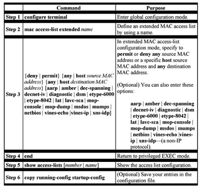
Use the no mac access-list extended name global configuration command to delete the entire ACL. You can also delete individual ACEs from named MAC extended ACLs.
This example shows how to create and display an access list named mac1, denying only EtherType DECnet Phase IV traffic, but permitting all other types of traffic.
Switch(config)# mac access-list extended mac1
Switch(config-ext-macl)# deny any any decnet-iv
Switch(config-ext-macl)# permit any any
Switch(config-ext-macl)# end
Switch # show access-list
Extended MAC access list mac1
deny any any decnet-iv
permit any any
Creating MAC Access Groups
Beginning in privileged EXEC mode, follow these steps to create MAC access groups:
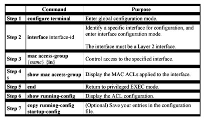
This example shows how to apply ACL 2 on Gigabit Ethernet interface 0/1 to filter packets entering the interface:
Switch(config)# interface gigabitethernet0/1
Router(config-if)# mac access-group 2 in
Note The mac access-group interface configuration command is only valid when applied to an a Layer 2 interface. If applied to a Layer 3 interface, the interface must have been configured with an IP address.
For inbound ACLs, after receiving a packet, the switch checks the packet against the ACL. If the ACL permits the packet, the switch continues to process the packet. If the ACL rejects the packet, the switch discards the packet. The MAC ACL applies to both IP as well as non-IP packets.
When you apply an undefined ACL to an interface, the switch acts as if the ACL has not been applied to the interface and permits all packets. Remember this behavior if you use undefined ACLs as a means of network security.
I hope you found this article to be of use and it helps you prepare for your Cisco CCNA certification. I am sure you will quickly find out that hands-on real world experience is the best way to cement the CCNA concepts in your head to help you pass your CCNA exam!