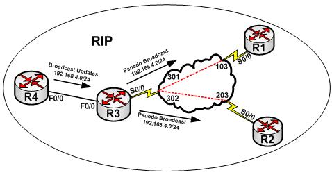
FIGURE-1: Pseudo Broadcast and Routing Protocols
In figure-1, the routing protocol is RIP version 1. R4 is advertising 192.168.4.0/24 to R3. Since updates are sent as broadcast, R3 will replicate the update as pseudo broadcast (or replicated unicast) to R1 and R2. The “frame relay map” statement requires the “broadcast” keyword for this functionality to be enabled. Otherwise, routing protocols like RIP, OSPF and EIGRP and other networking technologies relying either on broadcast or multicast will not work on Frame Relay networks.
Configuration:
Cisco IOS allows the emulating of broadcast (the pseudo broadcast) using the “broadcast” keyword at the end of frame relay DLCI mapping statement.
Step-1: configure terminal
Step-2: interface serial
Step-3: encapsulation frame-relay
Step-4: frame-relay map ip
Step-5: end
The IP address is the address of far-end device. For example, router-A is being configured to connect to router-B, the IP address of router-B is used. DLCI is local DLCI assigned by the service provider.
Pseudo broadcast is enabled (by-default) when Dynamic Inverse-ARP is used or frame relay is configured in point-to-point configuration. No explicit configuration is required for Inverse-ARP.
Let us consider an example. R3 (from figure-1) is being configured to communicate with R2 and R1. The ISP provided the following details:
- No Inverse-ARP
- DLCI for R1 circuit is 301
- DLCI for R2 circuit is 302
- Logical multipoint interface should be used.
The following will be the configuration script:
|
Configuration: |
|
R3(config)#interface serial0/0 R3(config-if)#encapsulation frame-relay R3(config-if)#interface serial0/0.123 multipoint R3(config-subif)#ip add 192.168.123.3 255.255.255.0 R3(config-subif)#no frame-relay inverse-arp R3(config-subif)#frame-relay map ip 192.168.123.1 301 broadcast R3(config-subif)#frame-relay map ip 192.168.123.2 302 broadcast R3(config-subif)#exit R3(config)# interface serial0/0 R3(config-if)# no shutdown R3(config-if)# end |
|
Verification: |
|
R3#show frame-relay map Serial0/0.123 (up): ip 192.168.123.1 dlci 301(0x12D,0x48D0), static, broadcast, CISCO, status defined, active Serial0/0.123 (up): ip 192.168.123.2 dlci 302(0x12E,0x48E0), static, broadcast, CISCO, status defined, active R3#show frame-relay pvc 302 PVC Statistics for interface Serial0/0 (Frame Relay DTE)
DLCI = 302, DLCI USAGE = LOCAL, PVC STATUS = ACTIVE, INTERFACE = Serial0/0.123
input pkts 8 output pkts 8 in bytes 832 out bytes 832 dropped pkts 0 in pkts dropped 0 out pkts dropped 0 out bytes dropped 0 in FECN pkts 0 in BECN pkts 0 out FECN pkts 0 out BECN pkts 0 in DE pkts 0 out DE pkts 0 out bcast pkts 0 out bcast bytes 0 5 minute input rate 0 bits/sec, 0 packets/sec 5 minute output rate 0 bits/sec, 0 packets/sec pvc create time 00:06:14, last time pvc status changed 00:02:56 R3#ping 192.168.123.2 Type escape sequence to abort. Sending 5, 100-byte ICMP Echos to 192.168.123.2, timeout is 2 seconds: !!!!! Success rate is 100 percent (5/5), round-trip min/avg/max = 96/145/272 ms R3# R3#ping 192.168.123.1 Type escape sequence to abort. Sending 5, 100-byte ICMP Echos to 192.168.123.1, timeout is 2 seconds: !!!!! Success rate is 100 percent (5/5), round-trip min/avg/max = 99/150/280 ms |
This brings us to the end of our discussion of Non-Broadcast Multi-Access networks.