Virtual Circuits can be categorized as either: permanent or switches (PVC and SVC).
Switched Virtual Circuits are on-demand and created for sporadic needs. Example: a phone call.
Permanent Virtual Circuits are dedicated link between two DTE nodes. Usually pre-configured by the service provider. The major advantage is that the repeated call setup and clearing is not required. However, PVCs are costly due to continuous circuit reservation.
ATM provides both SVC and PVC. Frame Relay is typically used to establish PVCs.
Design
Three types of design topologies can be used:
Full Mesh
Provides any-to-any communication. If there are “n” number of nodes in the network, total VC required are given by the formula: n(n-1)/2. For example: for 5 devices, 5(5-1)/2=10 VC are required. This is the trade-off between the availability and cost related to VC. Refer to figure-1 for details.
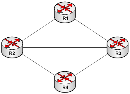
FIGURE-1: VC Full Mesh
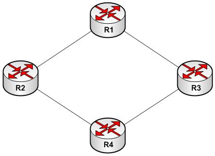
Partial Mesh
Figure-2 represents a partial mesh example. Not all the devices are connected to each other. The trade-off is the cost and availability. For example, if R1 losses connectivity to R3, it must be re-routed through R2 to reach R3.
Hub and Spoke (Star Topology)
Figure-3 depicts the hub and spoke network type. A central location is selected to terminate all the circuits. The main advantage is the administration of theses circuits and reduced cost. To provide, redundancy, another VC is required or ISDN could be used to establish on-demand circuits in case primary VC is lost.
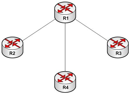
Figure-3: Hub and Spoke topology