Frame-Relay Basics
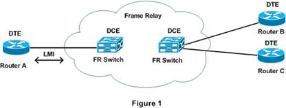
Frame-Relay networks are multi-access, meaning that multiple devices can be attached to the network similar to Ethernet LANs. But unlike LANs Frame-Relay networks do not support native broadcast but instead broadcast is replicated as unicast, thus this type of network is known as NBMA (Non-Broadcast Multi-access). Figure 1 shows an example of Frame-Relay Wide Area Network
We can consider Routers A, B and C as there sites of a company who have purchased Frame-Relay service from a provider. Each site connects with the Service Provider using a single link but using Frame-Relay technology virtual connection can be provisioned either on-demand or permanent to create various topologies like Hub-and-Spoke, Partial Mesh or Full Mesh. Figure 2 shows the concept of Virtual Circuits.
`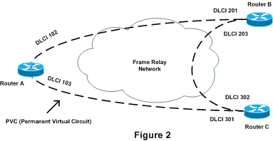
Table 1 specifies the various Frame-Relay Terminologies used in Figure 1 and 2.
|
Data Termination Equipment (DTE) |
These are usually customer owned devices such as Routers and are connected to Frame-Relay network of a Service Provider |
|
Data Communications Equipment (DCE) |
Frame-Relay switches in the Service Provider network are the DCE devices and they provide services like clocking and switching |
|
Local Management Interface (LMI) |
A signaling mechanism between a Router and a FR Switch for managing and maintaining a connection |
|
Virtual Circuit (VC) |
A logical connection between two DTE devices across a Frame-Relay network |
|
Permanent Virtual Circuit (PVC) |
Permanently established Virtual Circuits for frequent and consistent data transfer |
|
Switched Virtual Circuit (SVC) |
Virtual Circuits that are created on-demand on a temporary basis for sporadic data transfer and torn down when the data transfer is completed |
|
Data-Link Connection Identifier (DLCI) |
An address used to Identify a Virtual Circuit |
Frame-Relay Signaling and Encapsulation
LMI is signaling mechanism used between a Router (DTE) and Frame-Relay Switch (DCE) for managing and maintaining the connection between devices. A Cisco router supports three types of LMI mentioned below
- Cisco: LMI type defined by Cisco, StrataCom and DEC
- ANSI
- ITU-T Q.933A
A Frame-Relay router encapsulates a Layer 3 Packet in a Frame-Relay header and trailer. There are two options available on Cisco routers as mentioned below
- Cisco
- IETF
Frame-Relay Virtual Circuits
DTE devices exchange data over a frame-relay network by using virtual circuits. Multiple virtual circuits can be provisioned over a single physical link. Since SVCs are not in the scope of CCNA Certification, we will focus on the explanation and configuration of frame-relay PVCs. Each PVC at the DTE end is identified using a 10-bit address called Data-Link Connection Identifier (DLCI). As shown in Figure 2, Router A has two virtual circuits. A DLCI of 102 identifies the VC to Router B and 103 identifies a VC to Router C. At the other end on Router B a VC to Router A is identified by DLCI 201.
The DLCI is mapped to a Network layer destination address and when date needs to be transported over the frame-relay network to the remote destination it is encapsulated inside a frame-relay header. Each DLCI is mapped to a corresponding remote destination network address. As the frames are transported across the Provider, the frame-relay switch will change the DLCI values and when the frames are received the DLCI value will not be the same as it was when the frame entered the frame-relay network, hence the value of a DLCI is of a local significance only. Thus each Virtual Circuit between two DTE devices will have at least two DLCI. This type of addressing is known as local addressing
Frame-Relay Address Mapping
As mentioned previously frame-relay is non-broadcast multi-access media, which means that there must be a mechanism for Layer 3 to Layer 2 resolution. Consider figure 2, a company lets say ABC has purchased frame-relay WAN service from a provider to connect three of its offices. It will be using IP network 192.168.1.0/24 on the WAN.
Table 2 shows the WAN IP Address and Interface for each site
|
Site |
Interface |
IP Address |
|
Router A |
Serial 0/0 |
192.168.1.1/24 |
|
Router B |
Serial 0/0 |
192.168.1.2/24 |
|
Router C |
Serial 0/0 |
192.168.1.3/24 |
If Router A needs to communicate to Router B, it needs to map the IP Address of Router B to the local DLCI assigned by the Provider for the VC between A and B. Layer 3 to Layer 2 mapping can be done either manually or dynamically through the use of Inverse ARP.
Frame-Relay Interface
Apart from using the physical interface for Frame-Relay, Cisco IOS includes a feature called logical sub-interfaces.
An interface can be point-to-point which terminates a single VC or multipoint which can terminates more than one VC.
The Physical interface is a multipoint interface which can terminate multiple VCs. By using these features we can create various topologies such as Hub-and-Spoke, Full-Mesh or Partial Mesh.
By default LMI will associate all DLCIs to the physical interface. To associate an interface or a sub-interface with different DLCIs, frame-relay map or frame-relay interface-dlci commands are used.
Frame-Relay Configuration
We will use Figure 2 and Table 2 in this section for reference.
We will utilize the physical interface for Frame-Relay configuration and as previously mentioned the physical interface is a multipoint interface which can terminate more than one VC.
RouterA(config)# Interface Serial 0/0
RouterA(config-if)# ip address 192.168.1.1 255.255.255.0
RouterA(config-if)# encapsulation frame-relay
This will be the most basic configuration, and all other routers will be configured in a similar manner and only the IP Addresses at each router will be different.
Through the use of Frame-Relay LMI all DLCI will be assigned to the main interface and Inverse-ARP will dynamically map the IP Address to the local DLCI. If however Inverse ARP is disabled we can statically do the mapping as shown below.
RouterA(config-if)# frame-relay map ip 192.168.1.2 102 broadcast
RouterA(config-if)# frame-relay map ip 192.168.1.3 103 broadcast
Configuration using multipoint Interface
RouterA(config)# Interface Serial 0/0
RouterA(config-if)# no ip address
RouterA(config-if)# encapsulation frame-relay [ cisco | ietf ]
RouterA(config)# Interface Serial 0/0.1 multipoint
RouterA(config-subif)# ip address 192.168.1.1 255.255.255.0
RouterA(config-subif)# frame-relay map ip 192.168.1.2 102 broadcast
RouterA(config-subif)# frame-relay map ip 192.168.1.3 103 broadcast
Configuration using point-to-point Interface
Point-to-Point Interfaces can terminate only a single VC and each pair of sub-interface must have a unique subnet.
For the VC between Router A and B we have used 192.168.2.0/30 as the subnet.
RouterA(config)# Interface Serial 0/0
RouterA(config-if)# no ip address
RouterA(config-if)# encapsulation frame-relay [ cisco | ietf ]
RouterA(config)# Interface Serial 0/0.1 point-to-point
RouterA(config-subif)# ip address 192.168.2.1 255.255.255.0
RouterA(config-subif)# frame-relay interface-dlci 102
We have now completed an essential topic of CCNA Certification and most of the readers by now have a sound understanding of Frame-Relay concepts and configuration techniques.