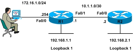
Figure 1
|
R1#sh run hostname R1 ip cef username cisco123 privilege 15 secret 5 $1$n4cI$7DU6SNLbO2J4sz6JnpOJB0 interface Loopback1 interface FastEthernet0/0 interface FastEthernet0/1 router rip R1# |
R2#sh run hostname R2 ip cef username cisco123 privilege 15 secret 5 $1$n4cI$7DU6SNLbO2J4sz6JnpOJB0 interface Loopback1 interface FastEthernet0/0 router rip R2# |
|
R1#ping 192.168.2.1 source 192.168.1.1 Type escape sequence to abort. |
As shown in the above output the routers are able to reach each other’s loopback interface.
We will now configure an ACL on R1 using SDM to deny ICMP traffic sourced from R2 loopback Interface and destined to R1 loopback interface
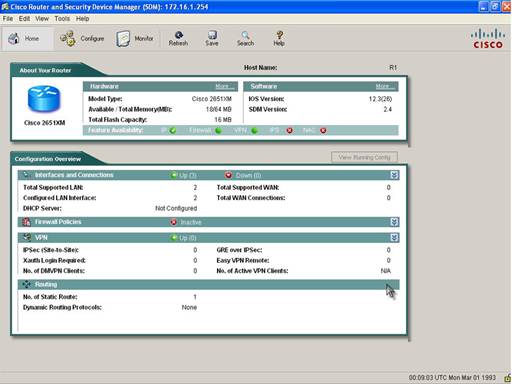
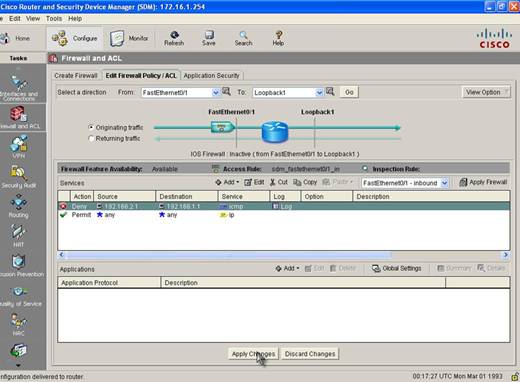
Step 1: Open Cisco Router and Security Device Manager
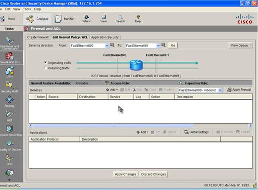
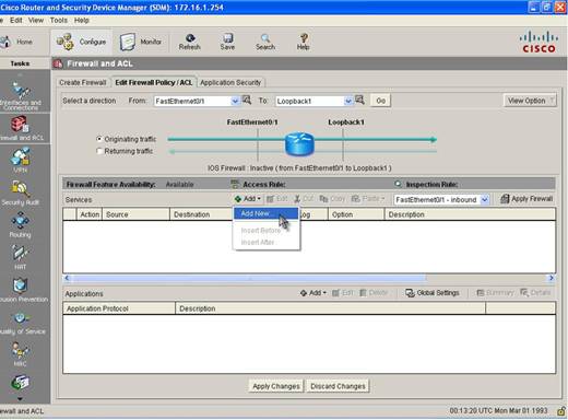
Step 2: Click Configure on the top menu and then Firewall and ACL button on the left Task Menu. Then click on the Edit Firewall Policy/ACL tab when Firewall and ACL page opens
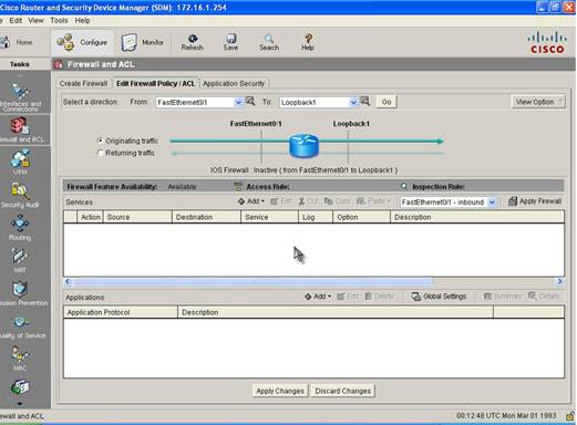
Step 3: Change Direction of ACL by Selecting Fast Ethernet 0/1 in the From drop-down menu and Loopback1 in the to menu because the ACL should be applied in the Inbound Direction on Fast Ethernet 0/1
Step 4: Add a New ACL by clicking the Add button and then Add New
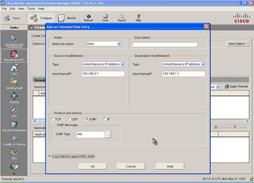
Step 5: A window will open that will allow you to an Extended Access-Control Entry (ACE). Select Deny Action and specify the Source and Destination IP Address and select ICMP as Protocol. We specified R2 Loopback IP address as the source and R1 Loopback IP address as the destination address.
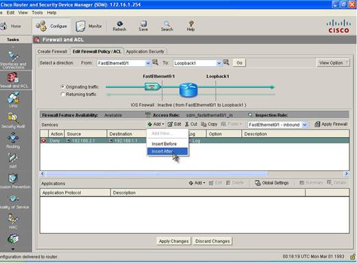
Step 6: We now need to add an Explicit ACE to permit rest of the traffic. We do so by inserting an ACE after the first ACE that we created.
Step 6: In the Add ACE window we will select Permit as the action and match any IP address as both source and destination and IP as the Protocol.
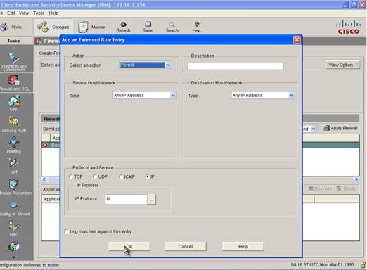
Step 7: Apply the ACL
Our ACL is now completed and we must now apply it. Once we do so SDM will send the commands to the Router. You can check the configuration of the Router to see what configuration was added by the SDM. Table below shows the configuration added by SDM.
|
interface FastEthernet0/1 ip access-list extended sdm_fastethernet0/1_in |
To check whether we fulfilled our requirement of denying ICMP traffic from R2 Loopback Interface to R1 Loopback Interface we will send ICMP traffic sourced from R2 Loopback Interface and destined to R1 Loopback Interface
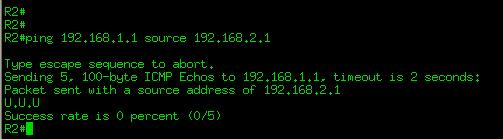
As shown the in the figure above ping is not successful, lets see if we can send other traffic
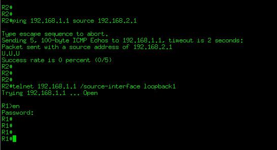
Ok! Our configuration is successful, we denied ICMP traffic between the loopbacks and allowed rest of the traffic.
Today we learned how to configure an ACL using Cisco Router and Security Device Manager. SDM is a very powerful tool that helps in configuring Cisco Routers. While preparing for CCNA Certification you must now both the Cisco IOS command line interface and Cisco SDM to configure routers.