We will use Figure 1 to explain these three problems.
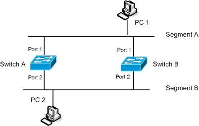
In the Figure above let’s assume PC-1 sends a frame to PC-2. This frame is received on Port 1 of both Switch A and Switch B. Since both switches do not know the destination address they simply flood the frame out all ports except the one it is received on, in this case Port 2. A copy of the frame is received on Port 2 of both Switches due each Switch sending the frame on Port 2 and other receiving the same frame from the other switch. The process repeats again and the flooding happens on the above segment. This goes on and on and a Broadcast Storm is created that consumes the entire resources of the network.
In the process described above PC-2 may receive multiple copies of same frame from Switch A and Switch B. This can cause problems as many protocols cannot handle duplicate frames.
Another problem that may be caused due to loops is instability of MAC address table. When PC-1 sends a frame to PC-2 and it is received on Port 1 of both Switches which then install PC-1 MAC address in the MAC address table and associate it with Port 1. Both Switches then flood the frame out Port 2. Switch A receives the frame that was flooded by Switch B and updates it MAC address table by associating PC-1’s MAC Address with Port 2. The same process happens on Switch B as well and the MAC table of both switches is corrupted and as a result traffic is switched out the wrong interfaces.
Spanning Tree Protocol was designed to avoid loops by finding redundant links in a network and shutting them down. To prevent bridging loops redundant paths must be identified and blocked. Not only does spanning-tree blocks redundant paths but also re-opens them in case of a link failure.
As the name implies, STP computes a tree that spans all switches in a network. All switches communicate using Bridge Protocol Data Units (BPDU) with each other. A reference point is agreed by all switches in a network and based on this reference point all redundant links are identified and blocked and only one path is allowed to forward traffic. If a link that was previously forwarding fails STP automatically enables one of redundant blocked links as the new active path.
Spanning Tree Workings
To obtain a loop-free topology STP uses three steps mentioned below
- Elect one Root Bridge
- Select one Root Port on the non-root bridges
- Select one Designated Port on each segment
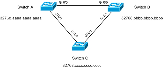
We will use figure 2 in our explanations for these three steps
Electing a Root Bridge
A Root Bridge is a reference point for all switches in a spanning-tree topology. Across all connected switches a process of election occurs and the Bridge with the Lowest Bridge ID is elected as the Root Bridge. Bridge ID is an 8-byte Value that consists of 2-Byte Bridge Priority and 6-Byte System ID which is the burned in MAC address of the Switch.
Initially all switches began advertising them selves as the Root Bride in BPDUs but once they receive a superior BPDU, one which has a lower Bridge ID, they cease the messages and starts forwarding the superior BPDUs .
In the above Figure all switches began with advertising themselves as the Root Bridge. When Switch B receives the BPDU from Switch A it compares the Bridge ID of itself with that of Switch A. Since the Priorities are same, the MAC address is used as the tie breaker and thus Switch A wins due to lower MAC Address. Switch B stops sending its BPDU and forwards the BPDU from A. This Process repeats on Switch C as well and it ceases the generation of BPDU and instead forwards BPDUs from A. Now a single reference point for the network is elected which is Switch A, all other switches now forward STP BPDUs received from Root Bridge.
Before we move on to next step we must know that every port in the Spanning-tree topology will end up in one of three Port Roles
- Root Port
- Designated Port
- Non-Designated/Blocking Port
Select one Root Port on the non-root bridges
Once a Root Bridge is elected all non-root Bridges elect a Root Port. This is a port that has the lowest cumulative path cost towards the Root Bridge. A Root Port is an upstream facing port that always points towards the Current Root Bridge.
Table 1 lists the Default Port Costs according to the IEEE 802.1D
|
Link Bandwidth |
STP Cost |
|
4 Mbps |
250 |
|
10 Mbps |
100 |
|
100 Mbps |
19 |
|
1 Gbps |
4 |
|
10 Gbps |
2 |
In Figure 2, as mentioned above Switch A will be the Root Bridge and it will send BPDUs out its interfaces every 2 Seconds with Root Path Cost of 0 as all its ports are attached to itself. Upon the receiving the BPDU Switch B and C will add the Path Cost of Port Gi0/0 which is 4. Both Switches then forward the BPDU with Root Path Cost of 4 out of Gi0/1 Interface. They will then receive BPDU from the other Switch on the Gi0/1 and add the Path Cost of 4.
Thus both Switches will have Root Path Cost of 4 on Gi0/0 and Root Path cost of 8 on Gi0/1 and as a result Gi0/0 will be the Root Port on both Switch A and Switch B
Select one Designated Port on each segment
The final step is to select one Designated Port on each segment. The Port that advertises the lowest Root Path Cost onto the segment is elected as Designated Port. Let’s Consider the Segment between Switch B and Switch C. Both Switches advertise 4 as the Root Path Cost, now there is a tie. Whenever selecting Root Ports or Designated Ports if two or more ports report the same Root Path Cost then the following tie breaker mechanism occurs
- Lowest Sender Bridge ID
- Lowest Sender Port Priority
- Lowest Sender Port Number
Thus port Gi0/1 of Switch B will be selected as the Designated Port for the segment between Switch B and Switch C as Switch B advertised lowest Bridge ID on to the Segment.
All ports of the Root Bridge are Designated Ports and any port that is not a Root Port or a Designated Port becomes the Blocking Port and is blocked to prevent loops.
Figure 3(a) shows the final converged loop-free topology. Port Gi0/1 of Switch C is put in the Blocking State and the loop is effectively removed and we obtain a topology similar to one in Figure 3(b).
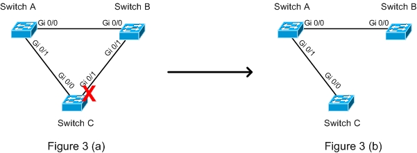
Note that if there are topological changes STP will re-converge. In case of a failure of the link between Switch A and Switch B the blocked port of Switch C will be put in to forwarding state.
When ever a Port is enabled and the STP process starts or whenever STP re-converges to a stable topology the Port has to transition different STP Port States. There are five STP Port states which are mentioned below
- Disabled
- Blocking
- Listening
- Learning
- Forwarding
All Ports when administratively shut down fall in the category of Disabled State. When a Port is enabled it will start in Blocking State to prevent any loops and thus no forwarding of traffic will take place neither the port will learn any MAC addresses. A Blocked Port will only process received BPDUs from neighboring switches.
A port that can be selected as Root Port or Designated Port will transition to Listening state. In this state the port will be allowed to send BPDUs as well so that it can actively participate in Spanning-tree.
After a period of time called Forward Delay (15 Seconds by Default) the Port can transition to Learning State in which it can learn MAC Addresses and send/receive BPDUs but still cannot forward or receive traffic.
After another Forward Delay the port is transitioned to Forwarding state and now it can send and receive traffic and is a fully functional port.