Configuring a Frame Relay Switch Lab B
These labs are not as good as the labs in our full blown CCNA Lab Workbook. The labs in our full blown CCNA lab workbook include theory as we step you through each lab, detailed information on why you are entering each command and review questions and answers at the end of the labs. So these labs are ok for free…but we offer a much better product consisting of 60 labs covering 400 pages of CCNA material to help you pass your CCNA Certification Exam in the workbook at this link CCNA Lab Workbook!
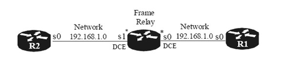
Objective: In this lab, you will configure a frame relay router and network. Once your configuration is complete, you will use basic techniques to test connectivity and view your DLCI mappings.
Hardware Requirements
• One router with two serial ports
• Two routers with one serial port
• Two back to back DTE/DCE serial cables
• IOS version 12.x or later
• A PC running a terminal emulation program
• Cisco console kit
Setup
• Configure the cabling as shown in the network diagram
• If the routers have a startup-config, erase it and perform a reload of the routers.
Configuration of the Frame Relay Router
Router>enable
Router#conf t
Router(config)#hostname FR
FR(config)#enable password cisco
FR(config)#frame-relay switching
FR(config-if)#int s0
FR(config-if)# no ip address
FR(config-if)# encapsulation frame-relay
FR(config-if)# clockrate 64000
FR(config-if)# frame-relay lmi-type ansi
FR(config-if)# frame-relay intf-type dce
FR(config-if)# frame-relay route 100 interface Serial1 200
FR(config-if)# no shut
FR(config-if)#int s1
FR(config-if)# no ip address
FR(config-if)# encapsulation frame-relay
FR(config-if)# clockrate 64000
FR(config-if)# frame-relay lmi-type ansi
FR(config-if)# frame-relay intf-type dce
FR(config-if)# frame-relay route 200 interface Serial0 100
FR(config-if)# no shut
FR(config-line)#line vty 0 4
FR(config-line)# password cisco
FR(config-line)# login
FR(config-line)#end
FR#write
Configuration of Router 1
Router>enable
Router#conf t
Router(config)#hostname R1
R1(config)#enable password cisco
R1(config-line)#line vty 0 4
R1(config-line)# password cisco
R1(config-line)# login
R1(config)#int loopback 0
R1(config-if)#ip add 1.1.1.1 255.255.255.255
R1(config-if)#no shut
R1(config-if)#int s0
R1(config-if)# encapsulation frame-relay
R1(config-if)# frame-relay lmi-type ansi
R1(config-if)# no shut
R1(config)#int Serial0.1 point-to-point
R1(config-subif)# ip address 192.168.1.1 255.255.255.0
R1(config-subif)# frame-relay interface-dlci 100
R1(config)#ip route 0.0.0.0 0.0.0.0 192.168.1.2
R1#write
Configuration of Router 2
Router>enable
Router#conf t
Router(config)#hostname R2
R2(config)#enable password cisco
R2(config-line)#line vty 0 4
R2(config-line)# password cisco
R2(config-line)# login
R2(config)#int loopback 0
R2(config-if)#ip add 2.2.2.2 255.255.255.255
R2(config-if)#no shut
R2(config)#int s0
R2(config-if)# no ip address
R2(config-if)# encapsulation frame-relay
R2(config-if)# frame-relay lmi-type ansi
R2(config-if)# no shut
R2(config-if)#interface Serial0.1 point-to-point
R2(config-subif)# ip address 192.168.1.2 255.255.255.0
R2(config-subif)# frame-relay interface-dlci 200
R2(config-if)#no ip classless
R2(config)#ip route 0.0.0.0 0.0.0.0 192.168.1.1
R2#write
Testing Connectivity of the Frame Relay Router
FR#sho frame route
Input Intf Input Dlci Output Intf Output Dlci
Status
Serial0 100 Serial1 200 active
Serial1 200 Serial0 100 active
FR#
Testing Connectivity of Router 1
R1#ping 192.168.1.2
Type escape sequence to abort.
Sending 5, 100-byte ICMP Echos to 192.168.1.2, timeout is 2 seconds:
!!!!!
Success rate is 100 percent (5/5), round-trip min/avg/max = 32/32/36 ms
R1#ping 192.168.1.1
Type escape sequence to abort.
Sending 5, 100-byte ICMP Echos to 192.168.1.1, timeout is 2 seconds:
!!!!!
Success rate is 100 percent (5/5), round-trip min/avg/max = 60/61/64 ms
R1#show frame-relay map
Serial0.1 (up): point-to-point dlci, dlci 100(0x64,0x1840), broadcast status defined, active
R1#sho ip route
(Output omitted)
Gateway of last resort is 192.168.1.2 to network 0.0.0.0
1.0.0.0/32 is subnetted, 1 subnets
C 1.1.1.1 is directly connected, Loopback0
C 192.168.1.0/24 is directly connected, Serial0.1
S* 0.0.0.0/0
R1#
Testing Connectivity of Router 2
R2#ping 192.168.1.1
Type escape sequence to abort.
Sending 5, 100-byte ICMP Echos to 192.168.1.1, timeout is 2 seconds:
!!!!!
Success rate is 100 percent (5/5), round-trip min/avg/max = 32/32/36 ms
R2#ping 192.168.1.2
Type escape sequence to abort.
Sending 5, 100-byte ICMP Echos to 192.168.1.2, timeout is 2 seconds:
!!!!!
Success rate is 100 percent (5/5), round-trip min/avg/max = 60/62/68 ms
R2#sho frame map
Serial0.1 (up): point-to-point dlci, dlci 200(0xC8,0x3080), broadcast status defined, active
R2#sho ip route
(Output omitted)
Gateway of last resort is 192.168.1.1 to network 0.0.0.0
2.0.0.0/32 is subnetted, 1 subnets
C 2.2.2.2 is directly connected, Loopback0
C 192.168.1.0/24 is directly connected, Serial0.1
S* 0.0.0.0/0 [1/0] via 192.168.1.1
R2#
Frame Relay Monitoring
The show interface or show interface serial are the most common commands which show a wide variety of information including showing you the DLCI used for LMI. When monitoring Frame Relay information on the router, a number of items are typically monitored including DLCI and LMI.
Router# debug frame-relay LMI command that you would use to monitor LMI information
Frame Relay Troubleshooting Commands
If a Frame-Relay DLCI attains a state other than “active” meaning inactive or deleted, you can check the Frame-Relay configuration to make sure its configuration matches the configuration of the router acting as the Frame-Relay DTE device.
Router# show frame-relay pvc – can be used to verify that the Frame-Relay PVCs are active and operational
Router# show frame-relay route – can be used to get a listing of the status of all the PVC’s
Router# show frame-relay map – can be used to verify that inverse ARP has successfully mapped remote network layer addresses to the appropriate DLCI.