Lab Setup
- Make the connection as per the topology.
- Use the IP addressing chart below to assign IP address to the routers.
- Make sure all three routers are configured with RIPv2. And can ping each other.
IP Addressing Schema
|
Router |
Interface |
IP Address |
|
R1 |
F0/0 |
100.1.12.1/24 |
|
F0/1 |
100.1.13.1/24 |
|
|
R2 |
F0/0 |
100.1.12.2/24 |
|
R3 |
F0/1 |
100.1.13.3/24 |
Lab Objective
Configure R1 to perform a generic TCP, UDP and ICMP inspection. Make sure that only the traffic that was initiated from inside is allowed back in. You should also allow the appropriate traffic through.
R1 Configuration
R1(config)#access-list 100 permit udp any any eq 520 (This ACL permits the UDP traffic of RIP)
R1(config)#access-list 100 deny ip any any log (Deny to generated log of UDP-RIP Traffic)
R1(config)#ip inspect name FW tcp (Inspect the tcp traffic) R1(config)#ip inspect name FW udp (Inspect the udp traffic) R1(config)#ip inspect name FW icmp (Inspect the icmp traffic)
R1(config)#int fa 0/0
R1(config-if)#ip access-group 100 in (Apply the ACL to interface)
R1(config-if)#ip inspect FW out (Apply the Inspection rule to interface)
Verification
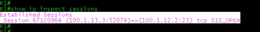
- To see the sessions, Telnet from R3 to R1, After telnet type the below mentioned command you will see the output , Once telnet session terminate , established sessions will gone.
R1#show ip inspect sessions
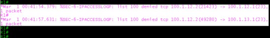
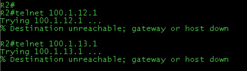
- When you trying to telnet from R2 (which is our outside network) you will get some log messages on R1, which looks like below.
And on R2 you will get the below messages.
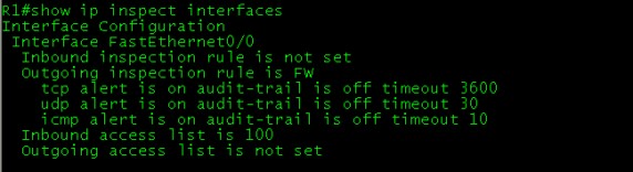
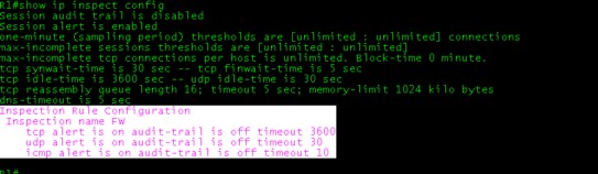
- To see the inspection configuration with this below mentioned command.
R1#show ip inspect config
- To see, where the inspection rule is applied use below mentioned command show ip inspect interfaces.