Local calls – happen between two telephones connected to a single cisco voice enabled router. This call is directly handled by the router and both telephone devices connect to Foreign exchange station (FXS) ports on the router. Here in call is switched between two ports on the same voice enabled cisco router. Figure 1 illustrates how local call works:
Figure 1: Local calls
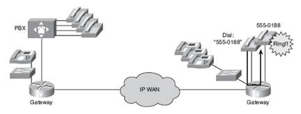
On net calls – on net calls happen between two telephones on the same data network the calls route through cisco voice enabled router and at the same time it remains on same data network. The edge telephone device connects to network through FXS ports or via PBX, which connects to network via T1 link. The IP phones connected to network via switches place on net calls using cisco unified communication manager. The connection could be LAN, or WAN connection. Figure 2 illustrates an on net call setup.
Figure 2: on net call setup
In this scenario a call is router via voice enabled router over an IP network and terminated at voice enabled router at remote office.
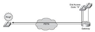
Off net calls – To get access to a PSTN line, user enters access code e.g. 9 from a telephone device connected to a voice enabled cisco router/PBX. It is usually a single analog connection via Foreign exchange office (FXO) port / digital T1/E1 connection. The call is routed via a voice enabled cisco router which is acting as gateway to the PSTN network. Figure 3 illustrates off net call setup.
Figure 3: off net calls setup
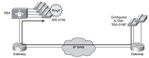
PLAR calls – These calls connect a telephone device to secondary telephone device when the first telephone device goes off hook. In this type of connection user will not get a dial tone because the voice enabled cisco router is preconfigured with a specific number. PLAR connection works between any type of signaling or any combinations of digital or analog interfaces. It is mainly used in customer servicing facilities. Figure 4 illustrates a PLAR call setup.
Figure 4: PLAR call setup
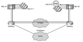
PBX – PBX calls – These calls originate at PBX at one site and terminate at a PBX at another site using the network as means of transport between two locations. Migration from converged voice and data network, the tie trunks connecting sites of same organization can be emulated across an IP network. In this scenario call is sent from local PBX, thru a voice enabled voice router and terminated on the remote office PBX. Figure 5 illustrates a PBX to PBX call.
Figure 5: PBX to PBX call setup
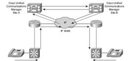
Intercluster trunk calls – In certain organizations PBX functionality is replaced by cisco unified communication manager to perform call routing functions which were provided by PBX. Calls are routed between cisco unified communication manager clusters using a trunk. Figure 6 illustrates an Intercluster trunk call setup.
Figure 6: Intercluster trunk call setup
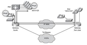
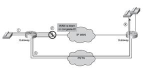
On net to off net calls – to have a redundancy in the event of failure of primary routing call path in an on net to off net call setup supports switching to failover path when a network link is down or if network is unreachable. Figure 7 illustrates on net to off net call setup.
Figure 7: On net – off net call setup
Voice ports on routers emulate physical telephony switch connections so that voice calls can be transferred between packet network and device. The signaling information needs to be sent across which is handled by installation of hardware device or by configuring the voice port which connect to telephony devices. Voice ports on gateways connect the router, access server or call control devices via signaling interfaces. These signaling interfaces generate information related to state of call such as on hook status, ringing and line seizure.
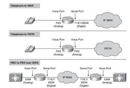
The voice port hardware or software will be configured to transmit and receive the similar type of signaling being used by the device to be interfaced to exchange calls smoothly between voice networks. Figure 8 illustrates the voice ports setup/ usage.
Figure 8: voice ports usage / setup
Voice ports can be analog or digital. Analog voice ports connect routers in packet based networks to analog two lines or four wire circuits in network telephony. Two wire circuits are meant for analog telephones and four wire circuits connect to PBXs. Cisco voice gateways support three types of analog voice interfaces as explained below and we will also learn how to configure them:
An FXS interface is used to connect an end user device to the router or access server. The FXS interface supplies ring, voltage and dial tone to station and has an RJ-11 connector for telephone equipment, PBX etc. FXS port usually function with default settings most of the time in USA which may not be true in case of other countries.
FXO is used for trunk, tie-line or connection to a PSTN CO or to a PBX. The RJ-11 modular telephone cable connects the FXO voice interface card to the PSTN or PBX via a telephone wall outlet.
E&M – Trunk circuits connect telephone switches to each other instead of end user equipment. An E&M interface uses special signaling path that are separate from the trunk audio path to send information about the calls.
To configure voice ports we need to enter voice port configuration mode.
Router (config) #voice-port slot port
Router (config-voiceport) #signal {loopstart | groundstart}
Router (config-voiceport) #cptone locale