- Performance improvement – Reduction in size of broadcast domain makes network devices run faster
- Enhanced Manageability – the logical division of networks into logical group of users, applications and servers helps to improve management of network in a better manner
- Independence from physical topology – VLANs allow to group of users regardless of there physical location. When departments grow in size or relocate to another location we can simply change the VLAN on their switch ports and there is no need to make any physical changes in the network
- Improved security – VLAN creates a logical boundary and to reach other subnets or VLANs one must have to pass through a layer 3 devices where we can add filtering options and implement other security features.
VLANs can also transcend switches; in such scenario switches must carry traffic from multiple VLANs. This kind of port is known as trunk port or tagged port because the switches send frames between each other with a VLAN “tag” in place. The VLAN tag is applied when a frame crosses a trunk port and it is stripped off when leaving the port to reach destination. All managed switched vendors support VLANs and to operate in a mixed vendor environment, a common Trunking or tagging is to be supported by all. This standard is known as 802.1Q. All managed switches support 802.1Q to support Trunking between switches in any environment.
It is standard practice to separate voice and data traffic using VLANs. Use of VLANs to separate voice and data traffic provides a security boundary as voice transmissions are susceptible to interception using a variety of applications namely wireshark and voice over mis-configured internet phones (VOMIT). Apart from this it helps to deploy other features such as QoS, prioritizing voice traffic over data and so on. The switching capability built into Cisco IP phones is as par with the external cisco switches. The incoming switch port receive and sends 802.1Q tagged packets and gives the capability to trunk between cisco switch and IP phones as depicted in figure 1.
Figure 1: voice and data traffic separation using VLANs
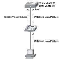
IP phone tags its own packets with the voice VLAN (VLAN 25) in the above figure , once the switch receives the tagged packets on a configured trunk port , the switch will read the tag and place data in the correct VLAN. The data packets go through the IP phone to switch untagged. The untagged packets are assigned to VLANs which is configured for data traffic on the switchport.
It is a quite tedious process to configure VLAN for networks for every switch in the organization so by using VTP (VLAN Trunking protocol) we can replicate VLANs over trunk links. A cisco switch is already configured as VTP server, which facilitate add / remove VLANs and replicate changes to other switches. Every VTP server has VLAN database, which contains information about all VLANs in an organization. The VTP server sends update to other VTP capable switches. VTP server is supported in three modes: VTP Server, VTP client and VTP transparent.
This is default mode of cisco switch. A VTP server can create/modify / delete /replicate VLANs to other switches in a network.
VTP client is not allowed to make any changes to VLAN database; it can only receive the changes from VTP server and apply them.
VTP transparent – it can create/modify/delete VLANs but replication is not allowed in this mode.
Now we look into how we configure VLANs and Trunking configuration. It involves five major steps as underline below:
Step 1: configure and verify VTP
Step 2: configure and verify 802.1Q trunks
Step 3: create VLANs
Step 4: Assign ports to VLANs
Step 5: configure routing between VLANs (optional step)
Configure and verify VTP – before we begin configuration of VTP in a VOIP network, first we need to verify the VTP because introducing a switch into network having existing VTP configuration will overwrite the existing VLAN database. The command used to verify VTP operation is:
Show vtp status
Output of command
VTP version: 2
Configuration revision: 0
Maximum VLANs supported locally: 1005
Number of existing VLANs: 5
VTP operating mode: server
VTP domain name:
VTP pruning mode: disabled
VTP V2 mode: disabled
VTP trap generation: disabled
MD5 digest: oxc4 oxAF oxA4 ox19 ox5F ox50 oxFO
This command shows vtp status and it has some key configuration items described below:
- VTP version/ VTP V2 Mode – Cisco default VTP version is 1. VTP version 2 supports VLAN on token ring networks.
- Configuration revisions – This is the current VTP database revision number, used by switches to determine current copy of VLAN database.
- VTP operating mode – switch currently set as VTP server, default mode in cisco switches
- VTP domain name – blank field indicates switch is not configured
We will use following parameters example to configure VTP Server.
Switch A
VTP mode: Server, VTP Domain: VOICE, VTP password: cisco
Switch B
VTP mode: Client, VTP Domain: VOICE, VTP password: cisco
SwitchA#configure terminal
SwitchA#vtp mode server
SwitchA#vtp domain VOICE
SwitchA#vtp password cisco
SwitchB#configure terminal
SwitchB#vtp mode server
SwitchB#vtp domain VOICE
SwitchB#vtp password cisco
You can use show vtp status command to verify the settings you have done on both switches
Configure and verify 802.1Q trunks – the next step is to configure 802.1Q trunks between the switches. To configure Trunking on switch port, we use switchport mode command. This command comprises of a set of parameters as described below:
SwitchA(config)#interface fastethernet 0/24
SwitchA(config)#switchport mode trunk
Switchport mode access command is required to configure port as nontrunking port. This command combats VLAN hopping attack, wherein a hacker tries to negotiate a trunked interface with a switch. This command disables this type of attack.
Switchport mode trunk command is required to configure a port as trunked connection. Whenever a devices attaches to other side it must be able to support tagged packets from the switch interface. On certain interfaces using switchport mode trunk command would result in an error message:
SwitchA (config-if)#switchport mode trunk
Command rejected: An interface whose trunk encapsulation is “auto” cannot be configured to “trunk” mode.
The error is result of multiple protocols support on switches for Trunking.
Before existence of 802.1Q cisco used its own proprietary Trunking protocol, this was slowly phased out by cisco. So until this protocol is completely phased out we need to add following command before adding switchport mode trunk command.
SwitchA (config-if)#switchport trunk encapsulation dot1q
SwitchA (config-if)#switchport mode trunk
These two commands will enable Trunking between switches.
In cisco switches dynamic negotiation of trunk ports is also supported mode. This is the default mode of all switchport in cisco. This mode means a switchport can dynamically become access port or trunk as per the device attached. But this dynamic mode can be used by hackers to launch a VLAN hopping attack.
The dynamic trunk negotiation mode is supported by a dynamic Trunking protocol (DTP). Cisco switches support multiple DTP modes as defined below:
Switchport mode dynamic desirable – In this default mode, cisco switches dynamically changes interfaces between access and trunk modes based on attached device.
Switchport mode dynamic auto – is able to dynamically change between access and trunk port configurations. But in case of using this mode, interface does not attempt to aggressively negotiate a trunk port connection unlike in dynamic desirable mode.
Switchport mode trunk – once interface is hard coded it cannot become an access port. But interface will keep on sending DTP packets and try to change other side of connection to trunk port, unless switchport negotiate command is given
Switchport mode access – The interface is hard coded as an access port and cannot become trunk port irrespective of any settings on other side
Switchport non-negotiate – This command disables DTP messages on interface
Once the trunk is configured we can verify the configuration using show interface
Out of switchport mode command as follows:
Switchport: Enabled
Administrative mode: trunk
Operational mode: trunk
Administrative Trunking encapsulation: dot1q
Operational Trunking encapsulation: dot1q
Negotiation of Trunking: ON
Administrative modes indicates what switch is configured to do and operational mode shows what actually it is doing.
Create VLANs- Once trunk is configured we can create VLANs, as VTP is configured, so when VLANs are created on switch A they will automatically replicated to switch B.
To create VLAN on switch A we issue following commands:
SwitchA#configure terminal
SwitchA(config)#vlan 10
SwitchA config-vlan)#name VOICE
SwitchA(config)#exit
SwitchA(config)#vlan 50
SwitchA(config-vlan)#name DATA
To verify VLAN configuration give command
Show vlan brief
Assign ports to VLANs – Now we can assign ports to each VLAN.
SwitchB#configure terminal
SwitchB(config)#interface range fa0/1 – 4
SwitchB(config-if-range)#switchport mode access
SwitchB(config-if-range)#switchport access vlan 50
SwitchB(config-if-range)#switchport voice vlan 10
The ports are configured to support a voice VLAN of 10 and a data VLAN of 50.
Configure routing between VLANs – With the current setup all data devices on VLAN 50 can reach each other but they cannot reach other networks. To configure inter VLAN routing we can go for three possible scenarios or designs:
- Separate router ports configured per VLAN
- Router connected to trunk port
- Layer 3/multiplayer switching
Separate ports on VLAN – We can use this design and plug a router interface into each VLAN. PCs on that VLAN will use router as the default gateway. This is a costly proposition because each VLAN requires a unique router port.
Router connected to trunk port – design enable to route between VLANs using a single router interface connected to a switch trunk port.
Layer 3/multiplayer switching – This type of inter VLAN routing uses a router integrated into a switch. Here the router is internal to the switch. To facilitate routing within the switch we have to configure switched virtual interfaces (SVIs). Once SVI is created all users in the SVI VLAN will be able to reach the interface. This design is considered superior as there is no bandwidth constraints for the hosts assigned to the VLAN to reach the router.
In a voice and data network design, a CME router can also act as router connected to port to route between voice and data VLANs. We can configure a trunk to the CME router using following commands:
SwitchA#configure terminal
SwitchA(Config)#interface fa0/20
SwitchA(config-if)#description CONNECTION TO ROUTER-ON-A-STICK CME ROUTER
SwitchA(config-if)#switchport trunk encapsulation dot1q
SwitchA(config-if)#switchport mode trunk
This concludes the lesson of CCNA voice exam on configuring switched infrastructure for voice and data networks VLANs.