Bandwidth – is usually referred as number of bits per second that can be successfully delivered across a link. Bandwidth can be equal to physical link speed in certain cases, or smaller or lower than the speed of physical link at times. In Point to Point links bandwidth is usually equal to port speed on physical link. The committed information rate or CIR defines the guaranteed bandwidth by provider that passes through their networks between the two DTE at each end of virtual circuit (VC). In Frame relay multi-access networks, actual CIR needs to be considered because in effect the bandwidth per VC = CIR of each VC.
The number of calls and amount of data traffic needs to be anticipated over the WAN link, to calculate bandwidth requirements accurately. In VOIP it is crucial to include the overheads of lower layers in voice traffic.
We will use an example to illustrate this: if VOIP is running over and Ethernet LAN, we have to take into account the overhead due to Ethernet, IP and RTP.
Total packet size = (L2 header) + (IP+UDP+RTP header) + (Voice payload size in bytes)
PPS = (Codec bit rate in bits) + (voice payload size in bytes)
Bandwidth = total packet size (in bits) * PPS
While sending VOIP traffic over WAN, it is good to use low bit rate codecs. What types of enhancements can be implemented to allow more calls to be placed over WAN links? G.729 which has a MOS of 3.92 which is a good choice after G.711 which only consumes 26.4 kbps per call on a frame relay WAN connection. Therefore it can support 10 connections simultaneously over a WAN with 264K of bandwidth. In Cisco Communication Manager, different codecs can be configured for use to communicate between devices in different regions. The two most commonly used codecs in Cisco VOIP environments are G.711 and G.729. G.711 needs approximately 80 kbps including overhead, and G.729 requires 24 kbps including overheads. Figure 1 below illustrates the same concept as mentioned above.
Figure 1: use of codecs in WAN links
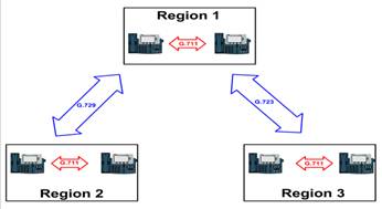
Phone in each reason is using codec G.711 on LAN. For the WAN G.729 and G.723 is being used which are low bit rate codecs.
In Cisco voice gateways the default codec used is G.729 for WAN dial peers. To change codec type we need to use codec
R1#Show running-config | begin dial-peer voice 2
!
Dial-peer voice 2 voip
Description ‘dial-peer to region 2’
Destination-pattern 2
Session target ipv4:150.1.1.2
!
Dial-peer voice 3 voip
Description ‘dial-peer to region 3’
Destination-pattern 3
Session target ipv4:150.1.1.3
The dial-peer in region 2 doesn’t show default codec, we can validate this using show dial-peer [options] command as illustrated below:
R1# show dial-peer voice 2 | include type|type|codec
Peer type = voice, information type = voice, numbering type = ‘unknown’
Type = voip, session-target = ‘ipv4:150:1.1.2’,
RTP dynamic payload type values = NTE = 101
RTP comfort noise payload type = 19
Codec = g729r8, payloadsize = 20 bytes,
Max redirects = 1, signaling type = cas,
We can also implement cRTP apart from using low bit rate codecs.
If we have less bandwidth available for voice calls, this will create unacceptable quality issues. Usually VOIP call follows a single path from end to end, that path may include LAN or WAN links, the slowest link presents the available bandwidth for the complete path – which is often referred as a bottleneck of the congestion caused by the slow link. In case of PBX environments, where data and voice bandwidth is segregated, users are not used to voice crackling, echoing, or dropped calls which is high in VOIP networks.
Voice traffic is predictable in nature as compared to data traffic; apart from bandwidth requirement voice traffic has some additional one way requirements:
- End to end delay: 150 ms or less
- Jitter: 30 ms or less
- Packet loss: 1% or less
Video traffic also has identical requirements of bandwidth as the voice traffic but it consumes a bit more bandwidth and the requirement may vary on how much movement is there in the video. The more the movement, bandwidth requirement will increase considerably.
If congestion is happening due to lack of bandwidth we can take certain measures to address that include the following:
Increase the bandwidth in case you are experiencing the congestion.
Queuing – procuring additional bandwidth has a cost impact, so instead of buying additional bandwidth, it is suggested to implement QoS. The QoS strategies used in Cisco Unified Communications are as follows:
Weighted Fair Queuing – (WFQ) – WFQ dynamically assigns the bandwidth to traffic flows once they arrive at router interface. Configuration is not required; and it is enabled by default on all routers links of T1 speed and below. This strategy is not suitable for VOIP networks as it does not guarantee bandwidth but allocates bandwidth based on flow sizes. VOIP requires a priority queue (PQ) which guarantees required bandwidth at the cost of all other traffic.
Class Based Weighted Fair Queuing (CWFQ) – This includes user defined classes for traffic. The admin classifies the traffic and assigns it queue.
Low Latency Queuing (LLQ) – LLQ extends the CWFQ along with PQ. PQ is reserved for voice traffic, and when packets are shown in PQ, they immediately sent, holding other packets in their respective queues. This is a preferred, method of queuing in VOIP networks.
Compression is another technique often used to optimize bandwidth. There are three types of compression techniques widely used.
Payload Compression: compacting the contents of data total packet size can be reduced.
Link Compression: on point to point links where header is not required we can use this compression method.
Header Compression: by using command RTP (cRTP), we can reduce layer 3 and 4 headers in VOIP networks from 40 to 2 bytes.
Delay – the delay is the time packet takes to reach its destination and it can come in three forms:
Fixed Delay – fixed delay cannot be changed it is the amount of time packet requires to travel specific geographical distances. QoS doesn’t manipulate this. The delays which impact quality of voice include:
- Codec delay
- Packetization delay
- De-jitter delay
Codec Delay is the amount of time used by digital signal processor (DSP) to compress a block of PCM samples. This is also known as processing delay, and it varies from voice coder used and speed of processor. Codec delay has two parts:
- Time needed to process incoming analog signals and do digital conversion of them.
- The look ahead feature.
All codecs have first factor applied to them. The IP phone or gateway needs to process the incoming analog signal and encode it into digital signal. Such as G.723.1 processes 30 ms of analog voice signal and G.729 needs 5 ms for the same. So choice of codec is a crucial factor.
Secondly, the look ahead feature, is based on a codec algorithm, codec look ahead features are available when it is predictive. CELP is a linear prediction based codec example; these algorithms require codec to posses some voice signals that can be encoded and next several ms of voice also.
For example with G.729 10 ms voice processing, requires codec must have initial 10 ms, plus next 5 ms to execute the predictive algorithm part. Codec delay is variable in nature and depends on codec load. Table 1 illustrates the best and the worst processing delay times for codecs.
Table: 1 Codec based processing delays (Best / Worst)
|
Coder |
Rate |
Required sample block |
Best case coder delay |
Worst case coder delay |
|
ADPCM, G.726 |
32 kbps |
10 ms |
2.5 ms |
10 ms |
|
CS-ACELP, G.729A |
8 kbps |
10 ms |
2.5 ms |
10 ms |
|
MP-MLQ, G.723.1 |
6.3 kbps |
30 ms |
5 ms |
20 ms |
|
MP-ACELP, G.723.1 |
5.3 kbps |
30 ms |
5 ms |
20 ms |
Packetization delays are related to time taken to fill a packet payload with encoded speech. This is also referred as accumulation delay; packetization delays can exist at both ends source and destination endpoints of a voice connection. At the source endpoint, the delay will vary as per the amount of time the endpoint takes to fill a packet with data.
Voice packets usually tend to be smaller in size, which helps to reduce the amount of latency added by the packet creation process. On the other endpoint the media gateway should remove and process the packet data. Any media gateway unit nominal operation should not exceed 30 ms. Table 2 lists the packetization delay for codecs in Cisco IOS voice gateways.
Table 2: Packetization delay for codecs in Cisco IOS voice gateways
|
Coder |
Payload size (bytes) |
Packetization delay (ms) |
Payload size(bytes) |
Packetization delay (ms) |
|
PCM, G.711 |
160 |
20 |
240 |
30 |
|
MP-ACELP, G.723.1 |
20 |
30 |
60 |
60 |
|
MP-MLQ, G.723.1 |
24 |
24 |
60 |
48 |
|
ADPCM, G.726 |
80 |
20 |
120 |
30 |
|
CS-ACELP, G.729 |
20 |
20 |
30 |
30 |
Jitter (delay variations) – jitter explains packets having different delay between them; for example a voice packet need 100ms to reach destination while other packet takes 110ms to reach same destination ,so there is a delay variation of 10ms. Delays can be minimized using following strategies:
- Increasing the bandwidth of link
- Use of priority queuing (PQ) for delay sensitive traffic
- Use of compression techniques
Media gateways have play out or de-jitter buffers to do buffering of a packet stream to avoid packet jitter on voice waveform. Play out buffers minimizes the jitter effects, but jitter cannot be eliminated completely. In Cisco IOS gateways administrators could use playout-delay [options] command on voice port or dial peer, to configure the jitter buffer.
R1 (Config)# voice-port 1/0/0
R1 (Config-voiceport) # playout-delay?
Fax fax playout buffer delay in milliseconds
Maximum maximum playout buffer delay in ms
Minimum configure minimum playout buffer delay type
Mode configure playout buffer adaptation mode
Nominal nominal playout buffer delay, in ms
The mode option has two further sub options as follows:
R1 (Config)# voice-port 1/0/0
R1 (Config-voiceport) # playout-delay mode?
Adaptive DSP adapts jitter buffer to network conditions
Default default
Fixed fix jitter buffer at constant delay
In adaptive mode, the jitter buffer size and amount of payout delay are accommodated during the call, based on network conditions. In case of fixed mode, the jitter buffer size doesn’t adjust during the call and a constant playout delay is included. The default is to use adaptive mode.
The options for playout-delay command to configure dial peer in Cisco IOS voice gateway is given as below:
R1 (Config) # dial-peer voice 2000 voip
R1 (config-dial-peer) # playout-delay?
Fax fax playout buffer delay in milliseconds
Maximum maximum playout buffer delay in ms
Minimum configure minimum playout buffer delay type
Mode configure playout buffer adaptation mode
Nominal nominal playout buffer delay, in ms
The options are same as for voice port configuration but for dial peers.
There are some other sources of delays also which needs to be considered as given below:
- Serialization delay
- Propagation delay
- Queuing delay
- Network delay
- Forwarding delay
Serialization delay – is the insertion of a bit into links. It is the amount of time taken by a network device, to encode a packet onto the wire for transmission.
Propagation delay is the amount of time a single bit takes to get from one end to other end on a link. This delay occurs when bits traverse the link and it is impacted by medium distance and not by link speed or clock speed.
Queuing delay is experienced by packets when they wait for other packets to be sent. Queuing delay is the time which is spent in internal router buffers.
Network delay occurs within the network cloud, such as in case of frame relay networks. This could be due to factors such as queuing delay from provider.
Forwarding delay is amount of time between when a frame is received and when the packets have been placed in the output queue. Table 3 lists the type of delays and states whether they are fixed or variable in nature.
Table 3: types of delays (fixed/ variable)
|
Delays |
Fixed or variable |
|
Codec delay |
Fixed |
|
Packetization delay |
Fixed |
|
Serialization delay |
Fixed |
|
Propagation delay |
Variable |
|
Queuing delay |
Variable |
|
Variable |
Variable |
|
Forwarding delay |
Variable |
|
De-jitter delay |
Variable |
Packet loss – Packet loss could occur due to congestion or unreliable network link. It could happen due to variety of reasons:
Tail drop – when output queue is full arriving packets cannot be placed in queue. So any packets arrive after queue is full are dropped from tail and are irrecoverable.
Input drop – when input queue is full, arriving packets are dropped and lost. This indicates an overloaded router CPU which is a rare scenario
Overrun – could be result of CPU congestion, when packet cannot be assigned to a free buffer by router it is known as overrun.
Ignore – no buffer space available.
Frame errors – transmission problems creating CRC, giant or runt frames. It could be due to EMI or failing interface hardware.
Loss of packets can be reduced with the help of QoS such as LLQ and compression or increasing link speed. Some other strategies that can be adopted to prevent congestion:
Traffic shaping – this delays packets and sends them at maximum configured rate. So it delays transmission of traffic to avoid packet drops.
Traffic policing – this drops packets in access of a configured threshold. These packets will be retransmitted if the traffic is using TCP, but not in case of VOIP.
This concludes the CCNA Voice lesson on how voice quality is impacted by certain factors and what strategies we can adopt to address them. In the next CCNA Voice lesson, will understand about these strategies more in detail.