Analog is presented as a sine wave and analog data is generated as voltage. Analog signals have four main characteristics namely – amplitude, frequency, wavelength, and pulse.
Amplitude is measure of signal/wave strength at given point of time.
Frequency is number of times the wave’s amplitude cycle from its beginning point, to highest amplitude and its lowest amplitude and then back to its starting point over a fixed period of time.
Wavelength – difference between the corresponding points on a wave’s cycle, for example, between one peak and the next peak. Wavelength is inversely proportional to the frequency, so when frequency is higher wavelength is shorter.
Phase – indicates the progress of wave over time in relationship to a fixed point. Like if two waves start at the same time, with both being at their highest amplitude, the two waves would be in phase. In case both waves started at the same time, with the first wave starting at its lowest amplitude and the second wave starting at its highest amplitude, the waves would be said to be 180 degrees out of phase.
Now we will look more in detail about analog circuits and also what Cisco devices are used to connect to analog PSTN lines.
Analog circuits are still most widely used by telephony networks worldwide. Though penetration of digital circuits is on rise still analog lines span is more widespread. In order to place calls Cisco gateways need to connect to PSTN and place calls. The analog circuits supported by cisco are foreign exchange station (FXS), foreign exchange office (FXO) and Earth and Magneto (E&M). In the subsequent sections we will learn about components of an analog phones and signaling methods used by analog circuits.
The components of analog phone described as under:
- Receiver: the handset speaker
- Transmitter: The handset microphone
- 2-wire/4 wire hybrid: conversion of 2-wire from CO to 4-wire in phone
- Dialer (Pulse / Tone): Dialing keypad or rotary dial
- Switch hook: switches to close/ open circuit (on-hook/ off-hook)
- Ringer: indicates an inbound call
Analog voice ports interface connects to routers in packet based networks to analog 2-wire or 4-wire circuits in a telephony network. 2-wire circuit connects analog phone or fax device, and 4-wire circuit connects to PBXs. Given below is the description and function of analog interfaces:
Foreign Exchange Station (FXS) – Fax / analog phone is directly connected to FXS port. (CCNA Voice exam question). Switches (both CO and PBXs) and cisco gateways have FXS ports to connect to analog phone/ device. The switch/FXS gateway port provides voltage, ring and dial tone to the analog device it also has an RJ-11 connector for telephone device, key set and PBXs. It also has a direct connection to VOIP network and contains a coder-decoder (Codec) to convert analog signal to digital signal for packetization. An analog telephony adapter from cisco can be used as an alternate device for remote FXS-to-Ethernet converter to connect to an analog station to a VOIP network. Figure 1 illustrates how FXS connects:
Figure 1: FXS connectivity

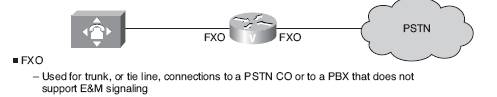
Foreign Exchange Office (FXO) – FXO ports connect to PSTN CO switch or to a PBX which doesn’t support E&M signaling. In order to connect gateway router to telephony CO on standard analog lines FXO ports are used. They allow gateway to place / receive calls to /from PSTN. FXO ports also have codec. Standard RJ-11 connects to FXO voice interface card to the PSTN or PBX via telephone wall outlet. Figure 2 illustrates how FXO connects:
Figure 2: FXO connectivity
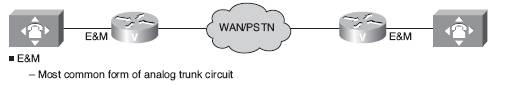
E&M – Also known as “Ear and Mouth” or “Receive and Transmit” or “Earth and Magneto”. These are analog trunks used to interconnect PBXs or tie-trunks. The naming history dates back to times when CO side had a key that grounded to the E circuit and other side had a sounder with an electromagnet attached to battery. There are separate leads for signaling and voice in E&M. One side of E&M is called trunk which is PBX side and other side is known as signaling unit side which is the CO, channel bank or cisco gateway E&M interface. The lead E indicate trunk side that signaling unit side is off-hook; and M lead indicates the signaling trunk side is on-hook. E&M interface has a DTE/DCE type interface. The trucking side is similar to DCE and other side is referred as signaling side is like DTE, and usually a device such as PBX. Figure 3 illustrates how E&M connects:
Figure 3: E&M connectivity
There are five types of E&M signaling – numbered 1 to type 5. Type II and V can be connected back to back in a Cisco gateway application but not type I. Cisco doesn’t support type V.
E&M signaling techniques are underlined below:
Wink Start – Cisco gateway on terminating side use a short off-hook/ on-hook wink as an acknowledgement that originating side (PBX) is gone off-hook. On received off-hook signal the originating side starts sending the digits and when the device at other end answer the call, the terminating side becomes off-hook and voice circuit is established.
Immediate Start – The originating side remains in the state of off-hook for a fixed amount of time (probably 200 ms) and the start transmitting digits irrespective of terminating side is ready to receive or not.
Delay Dial – When PBX is placing an outbound call to PSTN; PBX goes off-hook. The CO goes off-hook till it is ready to receive digits and then it goes on-hook / ready state. (This is delay dial signal). The PBX send the digits, when call is answered by device at other end the CO goes off-hook (This is called answer supervision) and voice circuit is up. The benefit of delay dial is in case equipment is not ready to receive digits immediately, and sent a wink; the delay is for compensation for the same.
This concludes our introduction on analog circuits, in the next lesson of CCNA voice exam we will learn about analog circuits and we also learn that how analog circuits have laid down the foundation for the way voice communication is happening in the telecom world.