Enterprise networks use digital circuits as compared to analog circuits while interconnecting VOIP network to traditional telephony environments, such as PSTNs or PBXs. Major benefits of using digital circuits is transportation of multiple conversations on a single line. A digital T1 circuit using channel associated signaling (CAS) can carry 24 parallel voice communications on a single circuit.
Another major advantage of a digital circuit is that it allows higher density of calls on a physical connection compared to an analog connection which can handle only one call at a time. Digital trunks are used to connect to PSTN, PBX or to the WAN. Basic rate interface (BRI) and primary rate interface (PRI) are commonly used trunks while connecting voice gateway to PSTN. There are two major categories of digital circuits – Common channel signaling (CCS) and Channel associated signaling (CAS). CAS signals are available in two speeds – T1 at 1.544Mbps which support 24 calls, E1 at 2.048Mbps which supports 30 calls. CCS circuits designated as – PRI T1, PRI E1 and BRI. A PRI T1 support 23 calls, PRI E1 supports 30 calls and BRI – 2 calls.
Digital voice ports are available at the intersection of a packet voice network and a digital circuit switched telephone network. There are three types of digital voice circuits supported by cisco voice gateways:
- T1: Use Time division multiplexing (TDM) for transmission of digital data over 24 phone channels using CAS
- E1: Use TDM for transmission of digital data over 30 phone channels using CAS or CCS
- ISDN: is a circuit switched telephone network system which uses CCS. Flavors of ISDN circuit include:
- BRI: 2 B (Bearer) channels and 1 D (Delta) channel
- T1 PRI: 23 B channels and 1 D channel
- E1 PRI: 30 B channels and 1 D channel
T1 circuits – In T1 circuit 24 channels are available for voice communication. Each conversation is loaded on a 64K channel and in case conversation cannot fill the entire channel it is filled with null values. And all 24 channels are ground together as one single frame. Whether 12 frames will be grouped together as one larger frame (known as super frame or SF) or 24 frames will be grouped together (known as extended super frame or ESF) depends on the type of implementation. T1 is full duplex (two wires for sending and two wires for receiving) and two way communication simultaneously.
E1 circuits – E1 is similar to T1 but with 32 channels, of which 30 channels are used for voice. The other 2 channels are used for framing and signaling. The 32 channels grouped together as a frame and 16 frames are grouped together as a multiframe. E1 circuits are used in Europe and Mexico.
Channel associated signaling (CAS) – T1 – In T1 all 64 k channels are used for voice but to transmit other information such as on-hook, off-hook, addressing etc, in CAS circuit the least significant bit of every channel is used for signaling bit strings. In 12 frame SF implementation one bit per channel in every 6th frame provides 12 bit signaling strings per SF. (also known as robbed bit signaling of (RBS)). (A and B string). A and B string used to indicate status, addressing and supervisory messages. In ESF allows A, B and C signaling strings to have more advanced signaling functions.
Channel associated signaling (CAS) – E1 – In case of E1the first channel (channel 0 or timeslot 1) is reserved for framing information. The 17th channel holds signaling information. Timeslots 2-16 and 18-32 are reserved for voice data.
Common channel signaling – CCS is used for completely out of band signaling channel. In ISDN PRI or BRI implementation it is the function of channel D. The 64K bandwidth per channel is meant for voice; a protocol Q.931 is used out of band in a separate channel for signaling. An ISDN PRI T1 has 23 voice channels (64K each) and one 64K channel D for data channel timeslot 24 for signaling. An ISDN PRI E1 gives 30 channels and 1 D channel (timeslot 17); ISDN BRI circuit has two 64 K B channels and one 16 K D channel.
The conversion of analog to digital signal is performed by a device called codec. There are four steps involve in the digitization of analog to digital signals we will discuss that in detail in subsequent sections.
- Analog sound sampling at regular intervals
- Quantize the sample
- Value encoding in binary expression
- Compress the sample (optional)
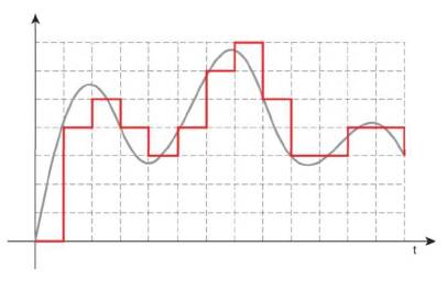
Analog sound sampling can be done at regular intervals like any number of times per second; the quality of audio would depend upon how frequently samples are taken. As per nyquist’s theorem the sample interval should be 2x highest sample frequency to have acceptable level of audio quality for playback. The highest quality in human speech is 4000 Hz; the sampling rate for standard quality of digital voice is 8000 intervals per second. The CD music, audio samples around 192,000 times per second as it need to encode both at higher and lower frequencies. Figure 1 illustrates digital signal pattern
Figure 1: Digital signal Pattern
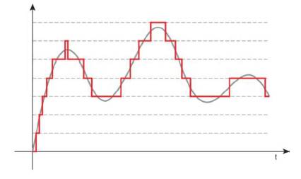
Digital approximation of an analog waveform is referred as quantizing. It is like you drawn an arc on a whiteboard; and you define the arc only using a square for each row (segment) and column (interval), that will give a stepped pattern close to original arc but not the exact. And this is what happens in quantizing: codec selects a segment value which is closer to analog value at the interval during sampling, may be not exact. In order to make quantization more accurate, sample can be divided into 16 intervals which are adjusted more closely to sample wave pattern. The segments are fine-grained at their origin point instead of lower / higher frequency ranges. Most human speech tired to be captured at the center range of scale, rather than very high/ very low values. Figure 2 illustrates digital signal quantization.
Figure 2 -Digital signal quantization
In signal encoding, a single 8 bit code word is used to identify in case analog signal was having positive or negative voltage, at what value signal was quantized (segment) and what interval is represented by the code word. The first bit indicates positive or negative voltage (1 + and 0 – ). The preceding 3 bits represent the segment. Eight segments are there in both positive and negative range and three bits provide the encoding information. The last 4 bits indicate the interval. We will take an example to illustrate this.
10011100
The 1st bit in this indicates a positive voltage the next digits of 001 indicate first segment and 1100 indicates the 12th interval.
The code word is 8 bit long and code word is generated 8000 times per second (sample rate). So the bit rate output = 8 X 8000 = 64,000 bps (64 Kbps). This process is known as pulse code modulation (PCM) and it is used as a standard for non-compressed digital voice in telephony. So one voice stream requires 64Kbps of transport bandwidth.
Often compression is used to save bandwidth on VOIP networks. There are two types of compression methods described below:
Adaptive differential PCM (ADPCM) – In this method entire code word is not sent, but a smaller code is sent which represents difference between the current word and the last word. This is not a very commonly used method of compression as it produces a low voice quality and compression is achieved only to about 16 Kbps.
Conjugate Structure Algebraic code excited linear prediction (CS_ACELP) – It is more complex method of compression. This is based on a standard dictionary of codebook of known sounds, the digital sample is analyzed and compared with this dictionary and the code matching the closet code word in dictionary is sent. The usual output of this compression is 8 Kbps – with very little fallback of voice quality and it is most widely used compression method in VOIP networks.
This concludes our introduction on digital circuits, in the next lesson of CCNA Voice exam we will learn about other components of a voice networks such as PBXs, trunk lines, key –systems and tie lines and we will also understand how all these components work in a voice network.