G.711 – it is the international standard to encode telephone audio on a 64Kbps channel. It operates at a 8 KHz sampling rate with 8 bits per sample. G.711 is ideal for digital voice delivery in PSTN/PBX or via PBXs. This is a popular means of telecommunication standard as it reduces signal to noise ratio without increasing any overheads.
The two subsets of G.711 codec are:
Mu-law– this is used in North America and Japanese phone networks.
A-law – this is used in Europe and rest of the world.
They both carry digitized speech in 8 bit sample and use 8 KHz sampling with 64Kpbs bandwidth demand.
G.726 – Is an ITU Adaptive differential pulse code modulation (ADPCM) coding at 40, 32, 24 and 16 Kbps. If PBXs support ADPCM; ADPCM encoded voice can be interchanged between packet voice, PSTN and PBX networks. Bit size of sample is used to refer four bits associated with G.726 which are 2 bits, 3 bits, 4 bits and 5 bits.
G.728 – It is a 16 Kbps low delay code excited linear prediction (LDCELP) variant of CELP voice compression. CELP needs to be translated into public telephony format for to/ through delivery via PSTN.
G. 729 – for compression to code voice into 8 kbps streams using conjugate structure algebraic code excited linear prediction (CS-ACELP). G.729a need less computation, but speech quality is worsened a bit. G.729b provides support for VAD and CNG, to have more efficient bandwidth usage. The features of G.729a and G729b can be combined together as G.729ab. These provide 6.4 kbps and 11 kbps rates for better voice quality.
G.723 is a dual rate speed coder used in multimedia communications. It compresses speed or audio signal at very low bandwidth. This codec has two bit rates as described under:
- R63: 6.3 kbps having 24 byte frames and MPC-MLQ algorithm
- R53: 5.3 kbps having 20 byte frames and ACLP algorithm
GSM full rate codecs (GSMFR): It has frame size of 20 ms and bit rate of 13 kbps, introduced in 1987. It is a RPE-LTP (Regular pulse excited – liner predictive) coder. VoiceXML scripts written to function as user interface for voice mail systems, GSMFR support is required. This codec is supported in Cisco infrastructure and application components of partners needed to deploy Unified Communication Solutions of service providers.
Internet low bit rate codec (iLBC): This is meant for narrow band speech, and having a payload bit rate of 13.33 kbps, 30 ms frames and 15.20 kbps for 20 ms frames. It is a variant of block independent linear predictive coding with frame length options as 30 ms and 20 ms respectively. The encoded blocks are encapsulated in transport protocol such as RTP.
There are three classes of vocoders or speech coders or voice coders namely waveform, source and hybrid. We will learn about them in detail:
Waveform codecs reconstructed signal whose waveform is as close as possible to the original without the knowledge of how signal to be coded was generated. Pulse code modulation (PCM) is the simplest way of waveform coding which simply involves sampling and quantizing the input waveform. Narrow-band speech is usually 4 kHz and sampled at 8 kHz. In linear quantization is used to have good quality speech around twelve bits per sample are needed, giving a bit rate of 96 kbits/s. The bit rate can be reduced by using non-uniform quantization of the samples. In speech coding an estimate to a logarithmic quantizer is often used. Such quantizer give a signal to noise ratio which is almost constant over a wide range of input levels, and at a rate of eight bits/sample (or 64 kbits/s) give a reconstructed signal which is almost indistinguishable from the original.
Source coders operate on the basis of how the source was generated, and attempt to extract, from the signal being coded, the model parameters. The model parameters are transmitted to the decoder. Source coders for speech are called vocoders, and work as follows. The vocal tract is represented as a time-varying filter and is excited with either a white noise source, for unvoiced speech segments, or a train of pulses separated by the pitch period for voiced speech. The information which must be sent to the decoder is the filter specification, a voiced/unvoiced flag, the necessary variance of the excitation signal, and the pitch period for voiced speech. This is updated every 10-20 ms to follow the non-stationary nature of speech.
The model parameters are determined by the encoder in a number of different ways, using either time or frequency domain techniques. There are varieties of ways to code information. Vocoders tend to operate around 2.4 kbits/s or below, and produce speech which although intelligible is far from natural sounding. Increasing the bit rate much beyond 2.4 kbits/s is not worthwhile because of the inbuilt limitation in the coder’s performance due to the simplified model of speech production used. The main use of vocoders has been in military applications where natural sounding speech is not as important as a very low bit rate to allow heavy protection and encryption.
Hybrid codecs try to fill the gap between waveform and source codecs. Waveform coders are capable of providing good quality speech at bit rates down to about 16 kbits/s, but are of limited use at rates below this. Vocoders on the other hand can provide intelligible speech at 2.4 kbits/s and below, but cannot provide natural sounding speech at any bit rate. The most commonly used hybrid codecs are time domain Analysis-by-Synthesis (AbS) codecs. Such coders use the same linear prediction filter model of the vocal tract as found in LPC vocoders. The excitation signal is chosen by attempting to match the reconstructed speech waveform as closely as possible to the original speech waveform. Atal and Remde introduced AbS codecs in 1982 and become to known as Multi-Pulse Excited (MPE) codec. Figure 1 illustrates the structure of AbS codec.
Figure 1: AbS codec structure
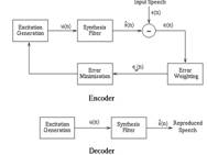
AbS codecs split the input speech to be coded into frames, (20 ms typically). For each frame parameters are determined for a synthesis filter, and then the excitation to this filter is determined. This is done by finding the excitation signal which when passed into the given synthesis filter minimes the error between the input speech and the reconstructed speech. Thus the name Analysis-by-Synthesis – the encoder analyses the input speech by synthesizing many different approximations to it. Finally for each frame the encoder transmits information representing the synthesis filter parameters and the excitation to the decoder, and at the decoder the given excitation is passed through the synthesis filter to give the reconstructed speech.
The differences between MPE, RPE and CELP codecs take place from the representation of the excitation signal u(n) used. In multi-pulse codecs u(n) is given by a fixed number of non-zero pulses for every frame of speech. Like the MPE codec the Regular Pulse Excited (RPE) codec uses a number of non-zero pulses to give the excitation signal u(n). However in RPE codecs the pulses are regularly spaced at some fixed interval and the encoder needs only to determine the position of the first pulse and the amplitude of all the pulses. The most commonly used algorithm for producing good quality speech at rates below 10 kbits/s is Code Excited Linear Prediction (CELP), proposed by Schroeder and Atal in 1985, and differs from MPE and RPE in that tin this the excitation signal is effectively vector quantized. The CELP coding principle has been very successful in producing communications to toll quality speech at bit rates between 4.8 and 16 kbits/s.
Sample size of voice determines the total bandwidth used. A voice sample is a digital output of a codec’s DSP encapsulated into a PDC (Protocol Data unit). Cisco voice equipments default encapsulation is 20 ms of audio in each PDU irrespective of the codec being used. We can configure to number of samples to be encapsulated. When more number of samples are encapsulated per PDU, total bandwidth required is less. But more sample encapsulation means larger PDUs which could result in delays and gaps in case PDUs are dropped. Table 1 shows number of packets required to transmit one sec of audio depending on varying sample sizes.
Table 1: voice sample size vs. packet size
|
Codec |
Bandwidth (Bps) |
Sample size (Bytes) |
Packets |
|
G.711 |
64,000 |
240 |
33 |
|
G.711 |
64,000 |
160 |
50 |
|
G.726r32 |
32,000 |
120 |
33 |
|
G.726r32 |
32,000 |
80 |
50 |
|
G.726r24 |
24,000 |
80 |
25 |
|
G.726r24 |
24,000 |
60 |
33 |
|
G.726r16 |
16,000 |
80 |
25 |
|
G.726r16 |
16,000 |
40 |
50 |
|
G.728 |
16,000 |
80 |
13 |
|
G.728 |
16,000 |
40 |
25 |
|
G.729 |
8000 |
40 |
25 |
|
G.729 |
8000 |
20 |
50 |
|
G.723r63 |
6300 |
48 |
16 |
|
G.723r63 |
6300 |
24 |
33 |
|
G.723r53 |
5300 |
40 |
17 |
|
G.723r53 |
5300 |
20 |
33 |
We can use a formula and determine the number of bytes encapsulated in a PDU based on the codec bandwidth and the sample size.
Bytes_per_sample = (sample_size * codec_bandwidth) /8
For example in case of G.711
Bytes_per_sample = (.020 * 640000) / 8
Bytes_per_sample = 160
The choice of codec for voice network depends on multiple factors such as is the codec supported on all VOIP devices in the network, number of DSPs (digital signal processor) resources required to code audio using the codec , bandwidth consumption by codec, packet loss handled by codec, codec support for multiple sample size and so on.
Deployment of codec in a WAN environment requires that we know the exact bandwidth requirement; various methods are used to determine the how much amount of bandwidth is required for the audio codec. We will learn in detail different methods in subsequent sections.
In order to determine the amount of bandwidth required for audio codec, we need to know size of audio contained in the packet. This size is determined based on the audio sample size within a packet. Generally in audio codecs, the sample size is 20 ms as default. Increasing in size of sample gives bandwidth savings as router needs to send less number of packets but the drawback of increasing sample size means overall delay in building the packet. When two devices are already in communication having significant delay, addition of coding delay would cause QoS issues. We can use a formula to determine the payload size
Byte_per_packet = (sample_size * codec_bandwidth) / 8
Sample_size variable use unit value of seconds and codec_bandwidth variable use a unit value of bits per second. So in case of using G.711 call using a 20 ms sample size, the formula calculation result in:
Bytes_per_packet = (.02 * 6400) /8
Bytes_per_packet = 1280 / 8
Bytes_per_packet = 160
Once we know the amount of voice contained in each packet we need to find out amount of data in header of each packet. Below is the list of values /overhead for common data link layer technologies:
Ethernet: 20 bytes, Frame relay: 4-6 bytes and PPP: 6 bytes
In OSI model, at network and transport layer values are as under:
IP = 20 bytes, UDP = 8 bytes and PPP = 12 bytes
Any other additional overheads in case we are using VOIP over a VPN connection. Based on type of VPN used overhead values are indicated as below:
GRE/L2TP: 24 bytes, MPLS: 4 bytes and IPsec: 50-57 bytes
Once we have all values, we can add them together to have final computation:
Total_bandwidth = packet_size * packets_per_second
For example if we are using, G.729 codec with 20 ms sample size over Ethernet, the packet size would be as under:
+ 20 bytes (voice payload) + 20 bytes (IP header) + 8 bytes (UDP header) + 12 bytes (RTP header) + 20 bytes (Ethernet header) = 80 bytes per packet
This derives the packet size. Now to know number of packets per second, we assume each packet contains 20 ms sample size, and 1 sec is 1000 ms, so if we take 1000 ms / 20 ms = 50 ms so that means it takes 50 packets per second to have full second of audio.
Total_bandwidth = packet_size * packets_per_second
Total_bandwidth = 80 bytes * 50 packets_per_second
Total_bandwidth = 4000 bytes per second
4000 * 8 = 32, 0000 bps (32 kbps)
This is how we find out amount of bandwidth consumed per VOIP call.
This concludes the CCNA Voice topic on codecs. In this lesson we learnt about types of codecs and how different codecs are used in VOIP networks. We also learned about calculating bandwidth use in VOIP networks and how it helps to make choice of codes to be used in voice networks.