The Cisco Unified CME supports three different models of configuration, we will learn about them in detail in subsequent sections. The three configuration modes are:
- PBX
- Key switch
- Hybrid
Each model represents a design which can be used by an organization.
PBX mode – the PBX system is quite similar to a small phone company inside the main phone company. The PBX is used to connect all of the individual lines within the company to the telephone truck lines in order to get the telephone access but the lines within the PBX all run in the internal telephone network.
In a PBX model, each IP phone is assigned a unique extension number. Figure 1 shows a PSTN call that is received at the Cisco Unified CME router, which sends it to the designated receptionist or automated attendant (1), which then routes it to the requested extension (2).
Figure 1: Cisco Unified CME PBX model (incoming call)
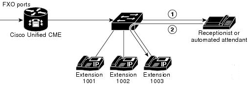
In PBX mode, users dial each other using their unique extension number. To dial outside the office phone network , they need to prefix 9 before (or any other access code), and get a second dial tone. A local receptionist or auto attendant system running on Cisco Unified CME will distribute calls from the PSTN to the users. In larger organizations where a direct inward dialing (DID) block of number is available, CME will route PSTN calls directly to the user. The phone users could be in separate locations or at different geographical location and still use the telephone system to contact each other.
In this mode it is recommended to configure directory numbers as dual-lines so that each button that appears on an IP phone can handle two concurrent calls. The phone user toggles between calls using the navigation button on the phone. Dual-line directory numbers enable the configuration to support call waiting, call transfer with consultation, and three-party conferencing (mentioned features are supported with G.711 only).
Key switch mode – Key switch mode is similar to TDM keyswitch environment which provides shared numbers to phones. In this model a receptionist is not used as it provides 1:1 ratio between directory numbers and PSTN circuits.
In a keyswitch system, most of the phones have nearly identification configuration, in which each phone is able to answer any incoming PSTN call on any line. This is meant for small offices where number of users is small and there is not often a need to use the telephone to contact each other.
For example, a 3×3 keyswitch system has three PSTN lines shared across three telephones, such that all three PSTN lines appear on each of the three telephones. This permits an incoming call on any PSTN line to be directly answered by any telephone—without the aid of a receptionist, an auto-attendant service, or the use of (expensive) DID lines. These lines are act as shared line, so a call can be put on hold on one phone line and resumed on another phone without invoking call transfer.
In the keyswitch model, the same directory numbers are assigned to all IP phones. When an incoming call arrives, it rings all available IP phones. When multiple calls are present within the system at the same time, each individual call (ringing or waiting on hold) is visible and can be directly selected by pressing the corresponding line button on an IP phone. In this model, calls can be moved between phones simply by putting the call on hold at one phone and selecting the call using the line button on another phone. In a keyswitch model, the dual-line option is rarely appropriate because the PSTN lines to which the directory numbers correspond do not themselves support dual-line configuration. Using the dual-line option also makes configuration of call-coverage (hunting) behaviors more complex.
You configure the keyswitch model by creating a set of directory numbers that correspond one-to-one with your PSTN lines. Then you configure your PSTN ports to route incoming calls to those ephone-dns. The maximum number of PSTN lines that you can assign in this model can be limited by the number of available buttons on your IP phones. Thus the overlay option may be useful for extending the number of lines that can be accessed by a phone.
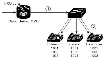
Figure 2 illustrates an incoming call from the PSTN (1), which is routed to extension 1001 on all three phones (2).
Figure 2 Incoming PSTN Call Using Keyswitch Model
This concludes the lesson on differences in PBX mode and key switch mode for telephony systems. In the next topic CCNA Voice topicwe will learn about different types of ephone and e-phone dns (commands used to configure directory of numbers in PBX and key system models).