Cisco CCNA Configuring Router Interfaces ( Chaoter 2 Contd)
In this section you will learn how to configure interfaces on a Cisco router.
Cisco CCNA Configuring an Interface
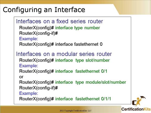
The type of interface includes things such as serial, ethernet, fastethernet, gigabitethernet, atm, tunnel, loopback, etc.
The number, slot/number and module/slot/number are numbers used to uniquely identify an interface on different types of routers.
Cisco CCNA Configuring an Interface
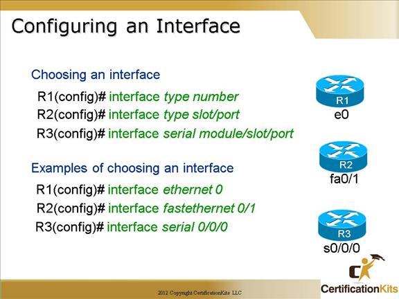
Some of the configurations used to configure an interface are Network layer addresses (IP Addresses), media type, bandwidth, and other administrator commands.
Different routers use different methods to choose the interfaces used on them.
Most of today’s routers are modular, the configuration would be “interface type slot/port” or “interface type module/slot/port”.
An example of configuring a fastethernet interface with some possible options is as follows:
interface fastethernet 0/0
ip address 192.168.1.1 255.255.255.0
Cisco CCNA Configuring IP Addresses
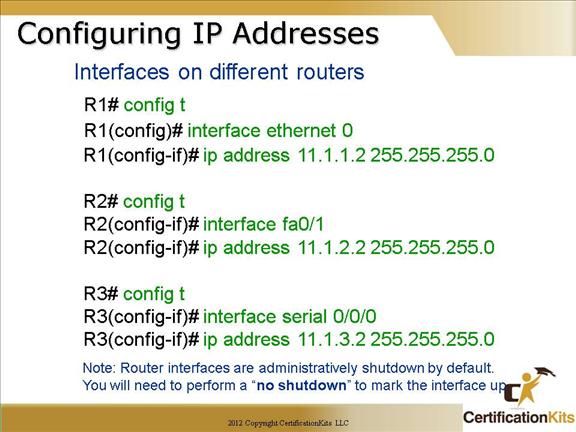
Even though you don’t have to use IP on your routers, it’s most often what people use. To configure IP addresses on an interface, use the ip address command from interface configuration mode.
Note: The command “ip address
Remember interfaces are administratively shutdown by default so you will need to perform a “no shutdown” for the interface to come up.
Cisco CCNA Serial Interface Clocking
 Cisco CCNA
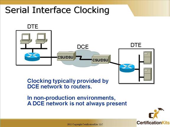
Serial interfaces will usually be attached to a CSU/DSU type of device that provides clocking for the line.
But if you have a back-to-back configuration (for example, one that’s used in a lab/classroom environment), on one end—the data communication equipment (DCE) end of the cable—must provide clocking.
The type of cable plugged into the serial interface can be verified by performing ‘show controller’ command. The clock present is representative of the cable plugged in (Data Terminal Equipment (DTE) or DCE). If it’s DCE, the ‘clock rate’ command will be needed in a back to back configuration.
Cisco CCNA Configuring a Serial Interface
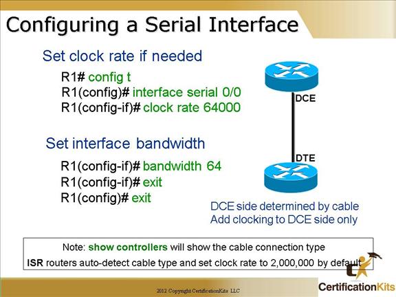
By default, Cisco routers are all data terminal equipment (DTE) devices, so you must tell an interface to provide clocking if you need it to act like a DCE device. You configure a DCE serial interface with the clock rate command.
The “show controllers command” displays information about the physical interface itself. It will also give you the type of serial cable plugged into a serial port. Usually, this will only be a DTE cable that plugs into a type of data service unit (DSU).
R1# show controllers serial 0/0
Hd unit 0, idb = 0x121c04, driver structure at 0x127078
Buffer size 1524, hd unit 0, v.35 DCE cable
The bandwidth and delay of an interface is used by routing protocols such as IGRP, EIGRP, and OSPF to calculate the best cost (path) to a remote network.
So if you’re using RIP routing, then the bandwidth or delay setting of an interface is irrelevant, since RIP uses only hop count to determine that.
Cisco CCNA Disabling or Enablng an Interface
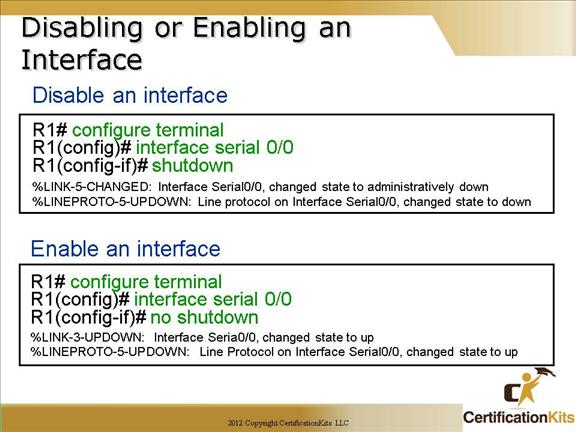
You can mark an interface administratively down with the “shutdown” command, and turn it on with the “no shutdown” command. If an interface is shut down, it will display administratively down when using the “show interface” command.
REMEMBER TO DO A “NO SHUTDOWN” COMMAND WHEN YOU HAVE CONFIGURED A DEVICE….THIS TRIPS UP MANY STUDENTS ON THE SIMULATION PORTION OF THE EXAM.
Cisco CCNA Verifying Your Changes
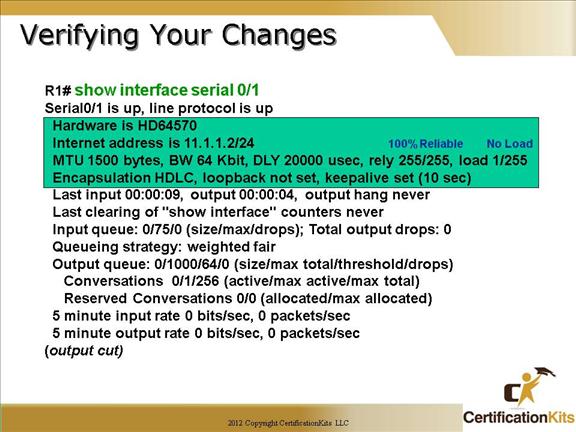
The command “show interface” reveals to us the hardware address (if a LAN interface), logical address, and encapsulation method, as well as statistics.
Maximum Transmission Unit (MTU) shows how many bytes of data can be sent in each encapsulated packet. BW is 1.544kbps by default on serial interfaces, Delay is 20,000 microseconds.
If the link is 100% reliable, the “rely 255/255” will be shown. If the link is basically at no load , the “load 1/255” will be displayed.
The encapsulation on a serial interface is HDLC by default. The loopback can be set to test the link and the keepalive is 10 seconds by default. This is a Data Link layer keepalive that is sent between routers. If the timers are not exactly the same, the Data Link layer will not come up.
Cisco CCNA Interpreting Interface Status
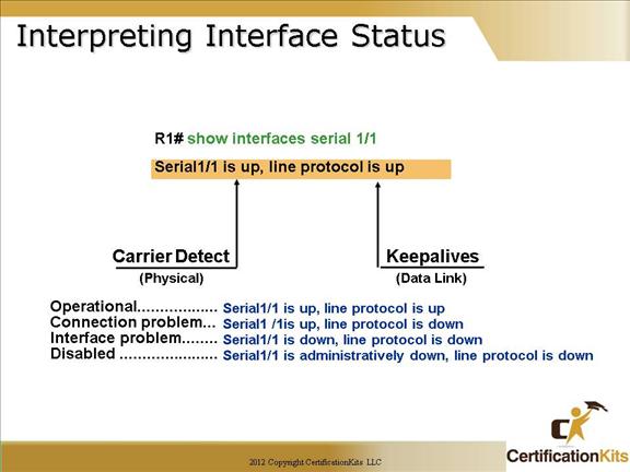
The most important statistic of the show interface command is the output of the line and data-link protocol status.
If the output reveals that serial 1/1 is up and the line protocol is up, then the interface is up and running.
The first listed “up” in this example, shows carrier detect from the CSU/DSU. The second “up” in this example shows keepalives from the remote router.
Another thing to confirm is the state of the signals. This is shown at the bottom of the output, and on most serial interfaces can also be seen on the router’s serial interface as a series of green lights. Usually when the router interface is up and normal, all of the signals will show to be up.
Cisco CCNA Show IP Interfaces Brief
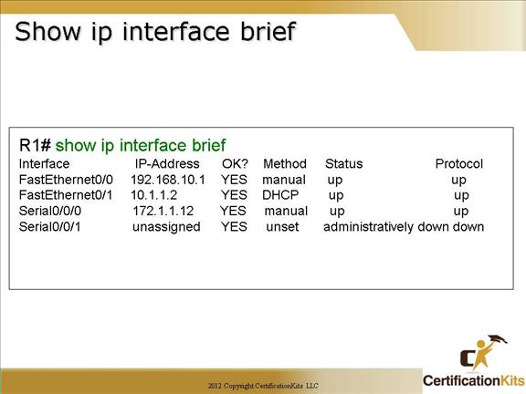
This command is used to get a quick view of the status of all interfaces configured on the router. The status and protocol fields are quick indicators as to the state of the interface. When you are troubleshooting if you see the status as administratively down, you need to perform a “no shutdown” on the interface to mark it administratively up. Prior to marking an interface administratively up, confirm that it should be up. Typically for security reasons unused interfaces are administratively marked down.
Cisco CCNA Which Issue on the left corresponds to the router output on the right?
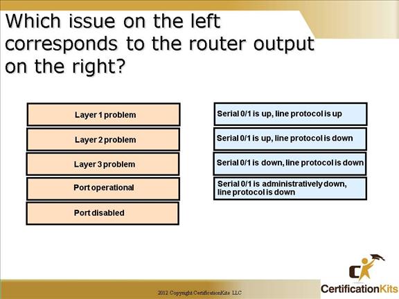
Answer:
Layer 1 problem – Serial 0/1 is down, line protocol is down
Layer 2 problem – Serial0/1 is up, line protocol is down
Layer 3 problem – no match
Port operational – Serial 0/1 is up, line protocol is up
Port disabled – Serial 0/1 is administratively down, line protocol is down
Cisco CCNA Erasing NVRAM on a Router
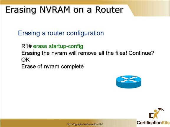
You can delete the startup-config file by using the “erase startup-config” command.
This command would be recommended if the router was being re-deployed or decommissioned, and you wanted to make sure none of the old configuration elements were present when it either comes back online, or is decommissioned. Once the configuration is erased, upon reboot of the router, the user will be prompted to enter setup mode as if the router had come from the factory. Setup mode can be utilized to initially configure basic things such as hostname, ip addresses on an interface, etc. If you rather entering initial configurations from regular configuration mode, you can exit out of the setup mode.
Note: The “write erase” command is another command that performs the same function.
Cisco CCNA Draw a line From the left to the answer on the Right….
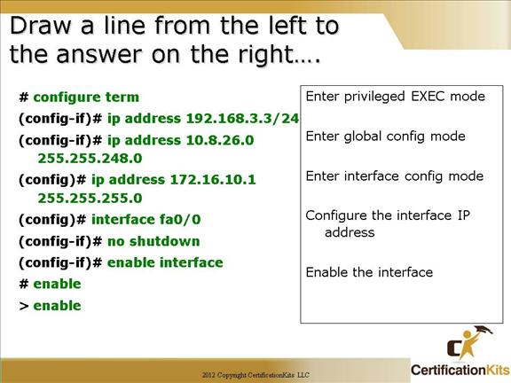
Answers:
Enter privileged EXEC mode – > enable
Enter global config mode – # configure term
Enter interface config mode – (config)# interface fa0/0
Configure the interface IP address – (config-if)# ip address 10.8.26.0 255.255.248.0
Enable the interface – (config-if)# no shutdown