Cisco CCNA Frame Relay
As a CCNA, you need to understand the basics of this technology and be able to configure it in simple scenarios. Realize that we are only introducing frame relay here, this technology is much deeper than we will explore in our current discussion.
Cisco CCNA Frame Relay Overview
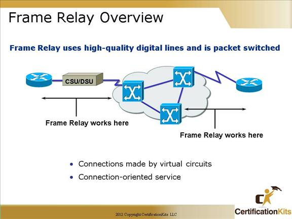
Frame Relay is used between the customer premises equipment (CPE) device and the Frame Relay switch. It does NOT affect how packets get routed within the Frame Relay cloud.
Frame Relay is a purely Layer 2 protocol.
The network providing the Frame Relay service can be either a carrier-provided public network or a network of privately owned equipment serving a single enterprise. It is more common to have a publicly provided frame relay network than to have a single enterprise attempt to manage or maintain their own frame relay network.
Cisco CCNA Frame Relay Stack
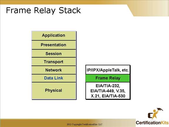
The same serial standards that support point-to-point serial connections also support Frame Relay serial connections.
Frame Relay operates at the data link layer.
Frame Relay supports multiple upper-layer protocols.
Cisco CCNA Frame Relay PVC (DLCI)
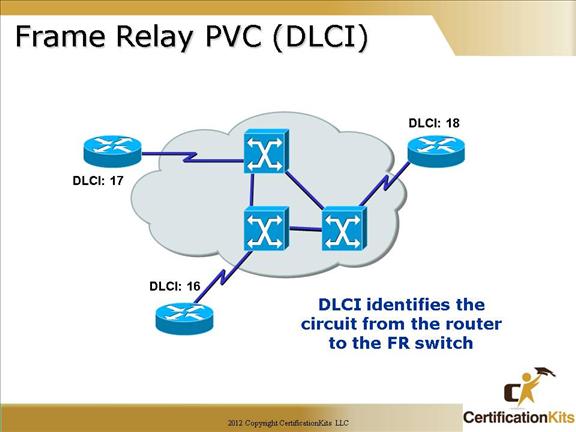
This figure provides an overview of terminology so that the student is prepared to understand the Frame Relay operation discussion.
The DLCI is of local significance, therefore, point out that the same DLCI can be used in multiple places in the network.
Frame Relay connections are made using PVCs. The circuits are identified by the DLCI assigned by the service provider.
Cisco CCNA DLCI’s are locally significant
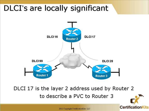
Frame Relay VCs use Data-Link Connection Identifiers (DLCI – pronounced “del-see”) as their addresses.
The locally significant DLCI must be mapped to the destination router’s IP address. There are two options for this, Inverse ARP and static mapping.
Cisco CCNA Frame Relay Mapping
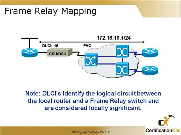
This figure illustrates mapping the data-link connection identifier (DLCI) to the network layer address such as IP.
The DLCI is of local significance, therefore, point out that the same DLCI can be used in multiple places in the network. Frame Relay connections are made using PVCs. The circuits are identified by the DLCI assigned by the service provider.
Static mapping can be configured instead of inverse ARP.
Cisco CCNA LMI
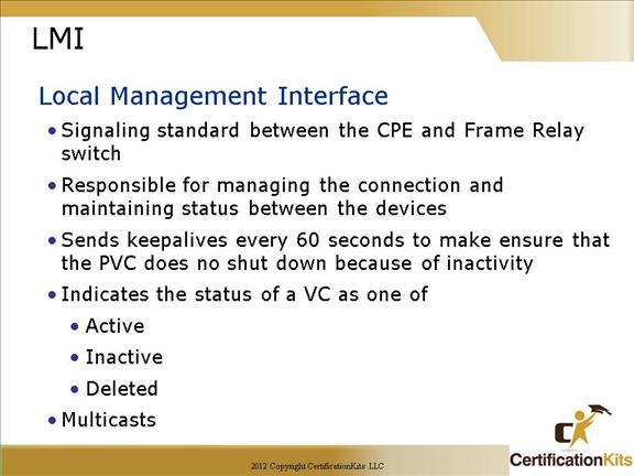
LMI is a signaling standard used between your router and the first frame relay switch it is connected to. It allows for passing of information regarding operation and status of the VC between the providers network and the DTE (your router).
Cisco CCNA LMI Standards
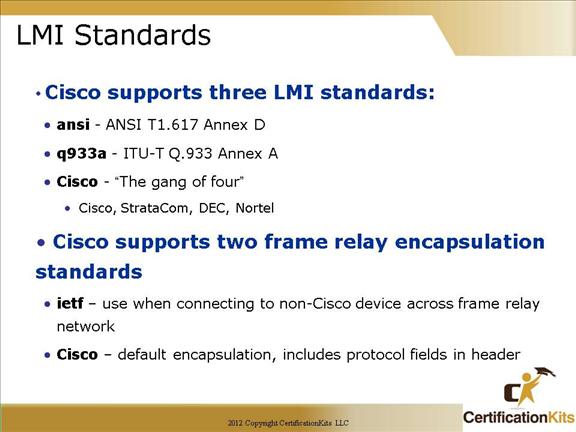
If you’re not going to use the auto-sense feature, you’ll need to check with your Frame Relay provider to find out which type to use instead. On Cisco equipment, the default type is Cisco, but you may need to change to ANSI or Q.933A if so instructed by your service provider. The three different LMI types are depicted in the following router output:
Cisco
LMI defined by the Gang of Four (default).
ANSI
Annex D defined by ANSI standard T1.617.
ITU-T (q933a)
Annex A defined by Q.933.
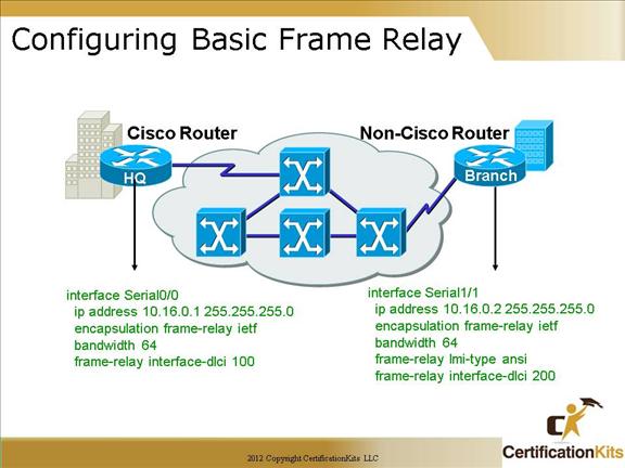
When configuring Frame Relay on Cisco routers, you need to specify it as an encapsulation on serial interfaces.
When you configure frame relay, you specify an encapsulation of frame relay.
However, unlike HDLC or PPP, with frame relay there are two encapsulation types: Cisco and IETF (Internet Engineering Task Force).
Cisco CCNA LMI and Encapsulation
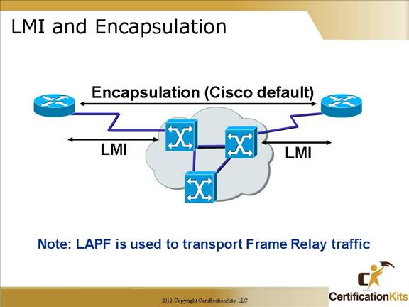
Local Management Interface (LMI) is a signaling standard used between the customer premise equipment (CPE) device, and a frame relay switch. It is responsible for managing and maintaining status between these two devices.
Cisco CCNA Frame Relay Inverse ARP and LMI Operation
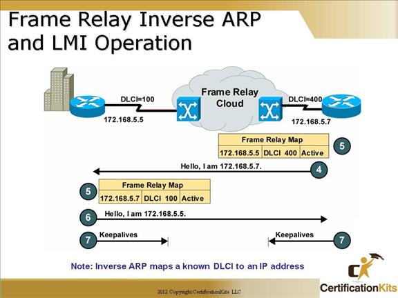
This figure describes the Inverse ARP and LMI process.
The LMI connection is established by the frame-relay lmi-type These configuration steps are the same, regardless of the network-layer protocols operating across the network. Cisco CCNA Configuring Basic Frame Relay This figure introduces basic Frame Relay configuration over a physical interface. These steps assume that LMI and Inverse ARP are supported, therefore no static maps are needed. Cisco’s Frame Relay encapsulation uses a 4-byte header, with 2 bytes to identify the DLCI and 2 bytes to identify the packet type. Use the ietf encapsulation command to connect to other vendors. The IETF standard is defined in RFCs 1294 and 1490. The LMI connection is established by the frame-relay lmi-type [ansi | cisco | q933a] command. The default values established during initial setup are usually sufficient to maintain connectivity with the Frame Relay network. Altering these values would only be required in case of intermittent failures. Changing the default values of the LMI should only be attempted after consulting with your service provider. These configuration steps are the same, regardless of the network-layer protocols operating across the network.