Cisco CCENT & CCNA Lab Kits – Click Here!
Cisco CCNA IP Addressing & Subnetting
One of the most important topics in any discussion of TCP/IP is IP addressing. An IP address is a numeric identifier assigned to each machine on an IP network. It designates the specific location of a device on the network.
An IP address is a software address (logical address), not a hardware address. IP addressing was designed to allow a host on one network to communicate with a host on a different network, regardless of the type of LANs the hosts are connected to.
Cisco CCNA Introduction to TCP/IP
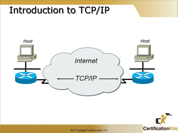
The Transmission Control Protocol/Internet Protocol (TCP/IP) suite was created by the Department of Defense (DoD) to ensure and preserve data integrity, as well as maintain communications in the event of catastrophic war.
So it follows that if designed and implemented correctly, a TCP/IP network can be a truly dependable and resilient one.
The Internet is built on a TCP/IP network.
Cisco CCNA Internet Protocol (IP)
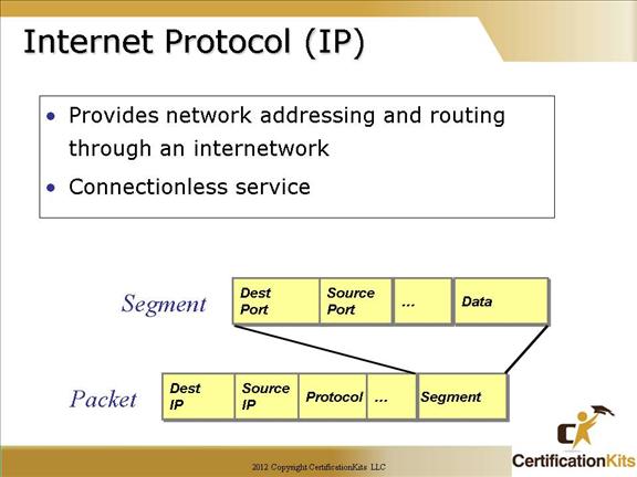
Internet Protocol (IP) essentially is the Internet layer. The other protocols found here merely exist to support it. IP holds the big picture and could be said to “see all,” in that it’s aware of all the interconnected networks. It can do this because all the machines on the network have a software, or logical, address called an IP address, which we’ll cover more thoroughly later in this chapter.
IP looks at each packet’s address. Then, using a routing table, decides where a packet is to be sent next, choosing the best path.
Cisco CCNA IPv4 Header
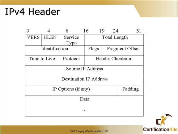
The fields in an IPv4 header are as follows:
Version – Indicates the version of IP currently used, currently 4
IP header length – Indicates the datagram header length in 32-bit words
Type of service (TOS) – Specifies how a particular upper layer protocol would like the datagram to be handled.
Total length – Length of the entire IP packet in bytes including data and header.
Identification – Used to help piece together data fragments. Contains an integer to identify the current datagram.
Flags – Three bit field used for fragmentation.
Fragment offset -Offset in the original datagram of the data being carried. Measured in 8 octets
Time to live (TTL) – Counter that is decremented as a packet traverses the network. Used to keep packets from looping endlessly.
Protocol – Indicates which upper layer protocol receives incoming packet after IP processing is complete.
Header checksum – Helps ensure IP header integrity.
Source address – IP address of sending node.
Destination address – IP address of receiving node.
Options – Allows support of various options.
Data – Contains upper layer information.
Cisco CCNA User Datagram Protocol vs. Transmission Control Protocol
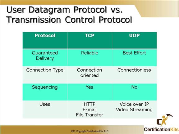
Reliable (Connection Oriented) – TCP is a reliable protocol that resides at the transport layer of the OSI reference model. It accounts for retransmission of lost data guaranteeing reliable delivery while also providing sequencing of packets so they can be re-ordered accounting for packet received out of order. Examples of applications that utilize TCP as a transport are HTTP, E-mail and FTP just to name a few.
Best Effort (Connectionless) – UDP is a best effort protocol that resides at the transport layer of the OSI reference model. It has much less overhead than TCP. It does not retransmit packets lost in transit nor does it provide sequencing to account for packets received out of order. A couple of examples of applications that utilize UDP are Voice over IP an Video Streaming.
Cisco CCNA User Datagram Protocol (UDP)
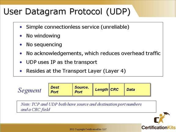
If you were to compare User Datagram Protocol (UDP) with TCP, the former is basically the scaled-down economy model that’s sometimes referred to as a thin protocol.
UDP doesn’t offer all the bells and whistles of TCP, but it does do a fabulous job of transporting information that doesn’t require reliable delivery—and it does so using far fewer network resources.
Like TCP, UDP resides at layer 4 of the OSI model and utilizes IP as the transport. It is a connectionless protocol that does not have windowing, sequencing or acknowledgements which are the things that make TCP a reliable protocol and UDP not a reliable protocol.
Cisco CCNA UDP Header
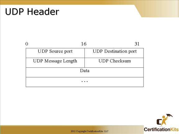
The fields in a UDP header are as follows:
UDP Source port – Optional, when specified, identifies the UDP source port. If not specified, should be zero.
UDP Destination port – Identifies the UDP destination port.
UDP Message Length – The number of octets that comprise user data and the UDP header.
UDP Checksum – Optional, a value of zero means the checksum was not used. Provides a way to ensure the data arrived intact.
Data – User data.
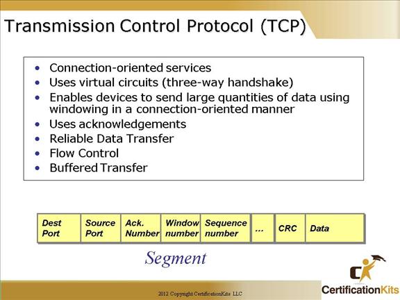
Cisco CCNA Transmission Control Protocol (TCP)
Since the upper layers just send a data stream to the protocols in the Transport layers, the Internet layer then routes the segments as packets through an internetwork.
The packets are handed to the receiving host’s Host-to-Host layer protocol, which rebuilds the data stream to hand to the upper-layer applications or protocols.
TCP creates a reliable sessions by setting up a virtual circuit (TCP connection), which includes acknowledgements, sequence numbers and windowing (flow control). TCP utilizes a three-way handshake to establish the TCP connection. The connection is uniquely identified by a combination of source ip address/port number and destination ip address/port number.
Cisco CCNA TCP Header
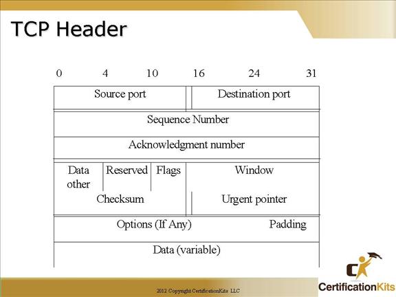
The fields in a TCP header are as follows:
Source port – Identifies the TCP source port.
Destination port – Identifies the TCP destination port.
Sequence number – Usually specifies the number assigned to the first byte of data in the current message. On connection establishment, identifies the initial sequence number to be used in the connection.
Acknowledgement number – Contains sequence number of the next byte of data the sender of the packet expects to receive.
Data offset – Indicates the number of 32 bit words in the TCP header.
Reserved – For future use.
Flags – Control information.
Window – Specifies the size of the sender’s receive window or in other words buffer space.
Checksum – Indicates whether the header was damaged in transit.
Urgent pointer – Points to the first urgent data byte in the packet.
Options – Specifies various TCP options.
Data – Contains upper layer information.
Cisco CCNA TCP Port Numbers
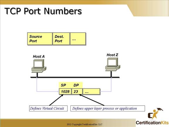
Examples of well known TCP and UDP port numbers:
HTTP (80), HTTPS (443) Telnet (23), FTP (21), SMTP (25): TCP
TFTP (69), SNMP(161): UDP
Originating-source port numbers are typically dynamically assigned by the source host and will equal some number starting at 1024 up through 65535. Port numbers with a value of 1023 and below are defined in RFC 1700, which discusses what are called well-known port numbers.
Virtual circuits that don’t use an application with a well-known port number are assigned port numbers randomly from a specific range instead. These port numbers identify the source and destination host in the TCP segment.
The different port numbers that can be used are:
Numbers below 1024 are considered well-known port numbers and are defined in RFC 1700.
Numbers 1024 through 65535 are used by the upper layers to set up sessions with other hosts, and by TCP to use as source and destination addresses in the TCP segment.
Cisco CCNA Setting Up A Reliable Session (Virtual Circuit)
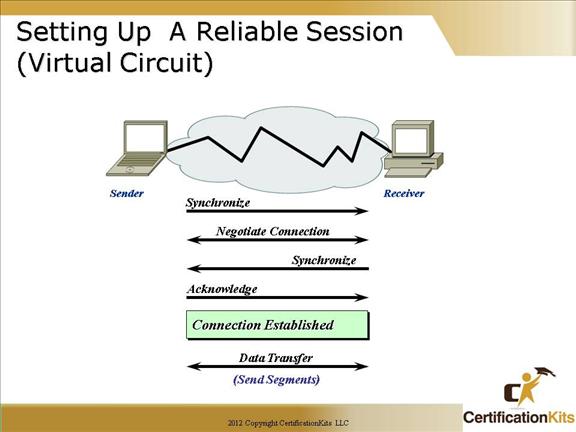
In reliable transport operation, one device first establishes a connection-oriented session with its peer system. This is called a call setup, or a three-way handshake.
Data is then transferred, and when finished, a call termination takes place to tear down the virtual circuit.
TCP uses a three-way handshake to establish a connection. The TCP three-way handshake is described in detail on the following slide.
Cisco CCNA TCP Connection Establishment
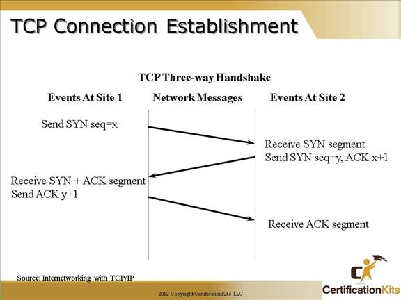
Shown in the slide is the TCP three way handshake used in establishing all TCP connections. The important thing here is the bits that are set with each packet (i.e. SYN, SYN+ACK, ACK).
As depicted, to establish a connection, TCP uses a three-way handshake. Before a client attempts to connect with a server, the server must first bind to a port to open it up for connections: this is called a passive open. Once the passive open is established, a client may initiate an active open. To establish a connection, the three-way (or 3-step) handshake occurs:
1. The active open is performed by the client sending a SYN to the server. It sets the segment’s sequence number to a random value A.
2. In response, the server replies with a SYN-ACK. The acknowledgment number is set to one more than the received sequence number (A + 1), and the sequence number that the server chooses for the packet is another random number, B.
3. Finally, the client sends an ACK back to the server. The sequence number is set to the received acknowledgement value i.e. A + 1, and the acknowledgement number is set to one more than the received sequence number i.e. B + 1.
At this point, both the client and server have received an acknowledgment of the connection.