Cisco CCNA TCP Flow Control
Data integrity is ensured at the Transport layer by maintaining flow control and by allowing users to request reliable data transport between systems.
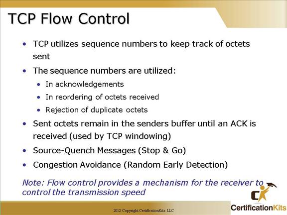
Flow control prevents a sending host on one side of the connection from overflowing the buffers in the receiving host—an event that can result in lost data.
Random Early Detection (RED) is a congestion avoidance mechanism that takes advantage of TCP’s congestion control mechanism.
Positive Acknowledgment and Retransmission (PAR) protocol consists of a sender, a receiver, and two unreliable communication channels for messages and acknowledgements.
A new message is sent only when the preceding one has been acknowledged. The sender detects the loss of a message (or acknowledgement) by using a timeout.
Cisco CCNA TCP Connection Establishment
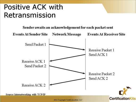
Each TCP packet send is ultimately acknowledged. If it is not acknowledged, it is retransmitted after a specified period of time.
Cisco CCNA Positive ACK with Retransmission
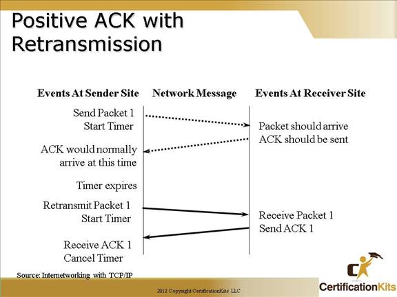
The slide above shows an example where packet 1 is sent but the sender does not receive it, hence an acknowledgement was never received prior to the timer expiring so packet 1 is retransmitted. The retransmitted packet is received and an acknowledgement is sent indicating receive of packet 1.
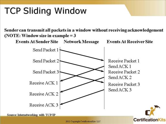
Cisco CCNA TCP Sliding Window
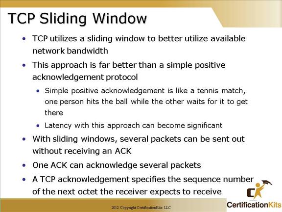
Buffers are used at each end of the TCP connection to speed up data flow when the network is busy. Flow Control is managed using the concept of a Sliding Window. A Window is the maximum number of unacknowledged bytes that are allowed in any one transmission sequence, or to put it another way, it is the range of sequence numbers across the whole chunk of data that the receiver (the sender of the window size) is prepared to accept in its buffer. The receiver specifies the current Receive Window size in every packet sent to the sender. The sender can send up to this amount of data before it has to wait for an update on the Receive Window size from the receiver. The sender has to buffer all its own sent data until it receives ACKs for that data. The Send Window size is determined by whatever is the smallest between the Receive Window and the sender’s buffer. When TCP transmits a segment, it places a copy of the data in a retransmission queue and starts a timer. If an acknowledgment is not received for that segment (or a part of that segment) before the timer runs out, then the segment (or the part of the segment that was not acknowledged) is retransmitted.
Cisco CCNA TCP Sliding Window
TCP Sliding Window Operation:
1. The current sequence number of the TCP sender is y.
2. The TCP receiver specifies the current negotiated window size x in every packet. This often specified by the operating system or the application, otherwise it starts at 536 bytes.
3. The TCP sender sends a datagram with the number of data bytes equal to the receiver’s window size x and waits for an ACK from the receiver. The window size can be many thousands of bytes!
4. The receiver sends an ACK with the value y + x i.e. acknowledging that the last x bytes have been received OK and the receiver is expecting another transmission of bytes starting at byte y + x.
5. After a successful receipt, the window size increases by an additional x, this is called the Slow Start for new connections.
6. The sender sends another datagram with 2x bytes, then 3x bytes and so on up to the MSS as indicated in the TCP Options.
7. If the receiver has a full buffer, the window size is reduced to zero. In this state, the window is said to be Frozen and the sender cannot send any more bytes until it receives a datagram from the receiver with a window size greater than 0.
8. If the data is not received as determined by the timer which is set as soon as data is set until receipt of an ACK, then the window size is cut by half. Failure could be due to congestion or faults on the media.
9. On the next successful transmission, the slow ramp up starts again.
Cisco CCNA TCP Reliable Session
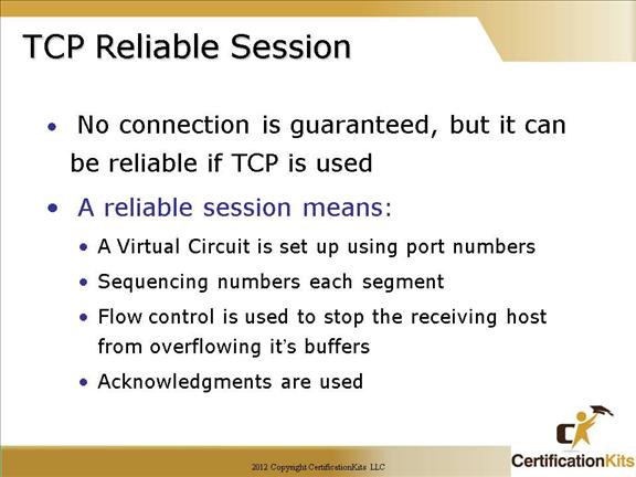
A reliable session is described as follows:
A Virtual Circuit is set up using port numbers
Sequencing numbers each segment
Flow control is used to stop the receiving host from overflowing it’s buffers
Acknowledgments are used in supporting reliable transport
Cisco CCNA Windowing & Acknowledgements
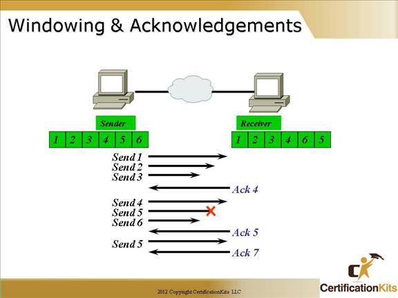
The quantity of data segments (measured in bytes) the transmitting machine is allowed to send without receiving an acknowledgment for them is called a window.
Reliable data delivery ensures the integrity of a stream of data sent from one machine to the other through a fully functional data link.
It guarantees that the data won’t be duplicated or lost.
This is achieved through something called positive acknowledgment with retransmission—a technique that requires a receiving machine to communicate with the transmitting source by sending an acknowledgment message back to the sender when it receives data.
Windowing is used to control the amount of outstanding, unacknowledged data segments.
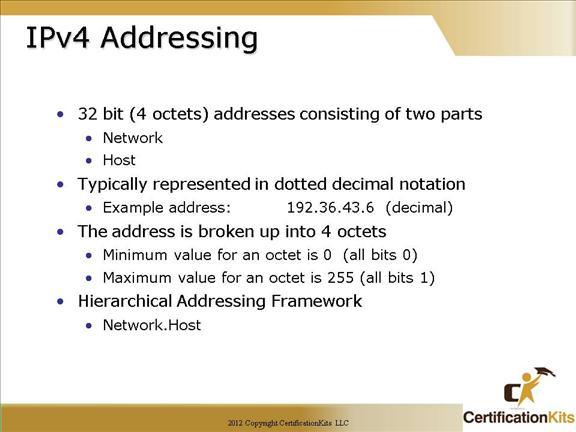
Cisco CCNA IPv4 Addressing
Before we get into the more complicated aspects of IP addressing, you need to understand some of the basics:
Defining basic IP addressing terms:
Bit = 1 digit (either a one or a zero)
Byte = 7 or 8 bits (depends on parity) From an IP address perspective, assume 8.
Octet = Always 8 bits
IPv4 addresses are 32 bit (4 byte) addresses consisting of two parts, a network portion and a host portion. It is typically represented in dotted decimal notation. An example is 192.36.43.6. Each octet has a value between 0 and 255 where 0 is all bits being 0 and 255 is all bits being 1.
Cisco CCNA IPv4 Addressing
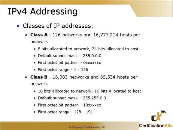
Defines Class A and Class B IP address characteristics.
Cisco CCNA IPv4 Addressing
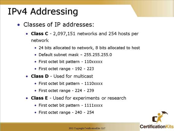
Defines Class C, Class D and Class E IP address characteristics.
Cisco CCNA IPv4 Special Addresses
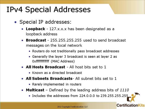
Local Broadcast Address
If an IP device wants to communicate with all devices on the local network, it sets the destination address to all 1s (255.255.255.255) and transmits the packet. For example, hosts that do not know their network number and are asking some server for it may use this address. The local broadcast is never routed.
Local Loopback Address
A local loopback address is used to let the system send a message to itself for testing. A typical local loopback IP address is 127.0.0.1.
Multicast Address
Special address similar to a broadcast address where one packet can be sent and received by multiple destinations. Receivers must subscribe to receive the ip multicast address to receive the multicast packets.
Auto configuration IP Addresses
When neither a statically nor a dynamically configured IP address is found on startup, those hosts supporting IPv4 link-local addresses (RFC 3927) will generate an address in the 169.254/16 prefix range. This address can be used only for local network connectivity and operates with many caveats, one of which is that it will not be routed. You will mostly see this address as a failure condition when a PC fails to obtain an IP address.
Cisco CCNA IPv4 Special Addresses
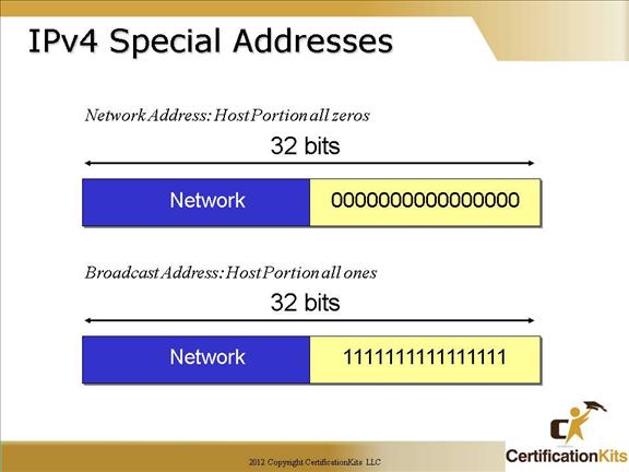
Network Address
An IP address that has binary 0s in all host bit positions is reserved for the network address. Therefore, as a Class A network example, 10.0.0.0 is the IP address of the network containing the host 10.1.2.3. As a Class B network example, the IP address 172.16.0.0 is a network address, while 192.16.1.0 would be a Class C network. A router uses the network IP address when it searches its IP route table for the destination network location.
The decimal numbers that fill the first two octets in a Class B network address are assigned. The last two octets contain 0s because those 16 bits are for host numbers and are used for devices that are attached to the network. In the IP address 172.16.0.0, the first two octets are reserved for the network address; it is never used as an address for any device that is attached to it. An example of an IP address for a device on the 172.16.0.0 network would be 172.16.16.1. In this example, 172.16 is the network address portion and 16.1 is the host address portion.
Directed Broadcast Address
To send data to all the devices on a network, a broadcast address is used. Broadcast IP addresses end with binary 1s in the entire host part of the address (the host field).
For the network in the example (172.16.0.0), in which the last 16 bits make up the host field (or host part of the address), the broadcast that would be sent out to all devices on that network would include a destination address of 172.16.255.255.
The directed broadcast is capable of being routed. However, for some versions of the Cisco IOS operating system, routing directed broadcasts is not the default behavior.