Cisco CCNA Show Interface Truck
To verify trunk configuration use one of the following two commands:
To display the administrative and operational status of a switching (nonrouting) port, use the show interfaces switchport command.
show interfaces
interface-id – (Optional) Interface ID for the physical port.
module mod – (Optional) Limits the display to interfaces on the specified module; valid values are from 1 to 6.
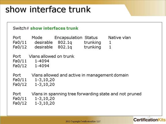
To display port and module interface-trunk information, use the show interfaces trunk command.
show interfaces trunk [module mod]
module mod – (Optional) Limits the display to interfaces on the specified module; valid values are from 1 to 6.
Cisco CCNA Configuration Question
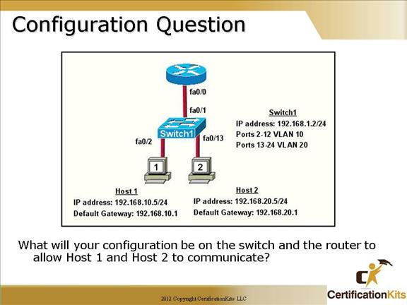
Answer:
Router(config)#int fa0/0
Router(config-if)#no shutdown
Router(config-if)#int fa 0/0.1
Router(config-subif)#encap dot1q 10
Router(config-subif)#ip address 192.168.10.1 255.255.255.0
Router(config-subif)#exit
Router(config)#int fa 0/0.2
Router(config-subif)#encap dot1q 20
Router(config-subif)#ip address 192.168.20.1 255.255.255.0
Switch1(config)#int fa 0/1
Switch1(config-if)#switchport mode trunk
Remember, router ports are administratively down by default so the “no shutdown” command is needed on the router but by default switch ports are administratively up so the command is not needed on the switch.
Cisco CCNA VLAN Question
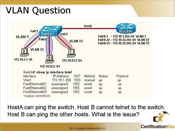
Hosts A, B and C are all configured on different subnets. Everything from the hosts perspective looks to be configured correctly. Note that host A is on VLAN1 while host B and C are on VLANs 32 and 33 respectively. Since host A can ping the switch, the only possible answer could be that the switch has an IP address define on VLAN 1 but does not have an “ip default-gateway” assigned.
Cisco CCNA Virtual Trunk protocol (VTP)
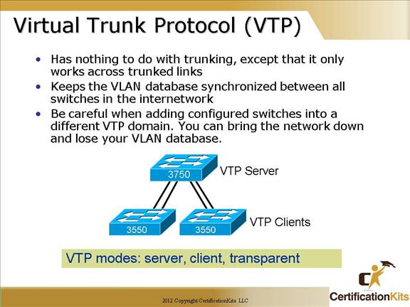
Server: This is the default for all Catalyst switches. You need at least one server in your VTP domain to propagate VLAN information throughout the domain.
The switch must be in server mode to be able to create, add, or delete VLANs in a VTP domain.
Client: switches receive information from VTP servers, and they also send and receives updates. But they can’t make any changes.
Learns and saves VTP configuration in the running configuration but does not save it to NVRAM.
Transparent: Switches don’t participate in the VTP domain, but they’ll still forward VTP advertisements through any configured trunk links.
Passes information about VTP configuration only.
Be careful when adding configured switches into a different VTP domain. You can bring the network down and lose your VLAN database.
Cisco CCNA VTP Modes
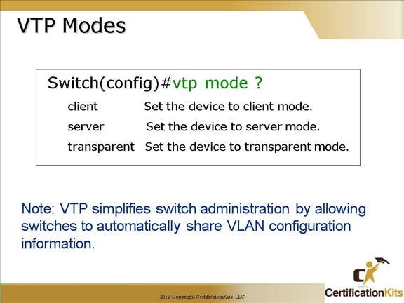
The VTP mode is changed from global configuration mode with the following command:
vtp mode mode
Where mode is either client, server or transparent.
Server: This is the default for all Catalyst switches. You need at least one server in your VTP domain to propagate VLAN information throughout the domain. The switch in server mode can create, add, or delete VLANs in a VTP domain.
Client: switches receive information from VTP servers, and they also send and receives updates. But they can’t make any changes. Learns but DOES NOT save VTP configuration in the running configuration and does not save it to NVRAM, nor anywhere else. It learns and forwards VTP information only. Client switches cannot create, add or delete VLANS.
Transparent: Switches don’t participate in the VTP domain, but they’ll still forward VTP advertisements through any configured trunk links. Passes information about VTP configuration only. Can create, add, or delete VLANs on the local switch.
Cisco CCNA VTP Client Mode
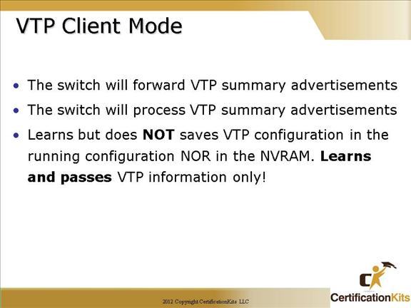
In Client Mode,
The switch will forward VTP summary advertisements
The switch will process VTP summary advertisements
The switch learns but does NOT saves VTP configuration in the running configuration NOR in the NVRAM. Learns and passes VTP information only!
Cisco CCNA VTP Configuration Example
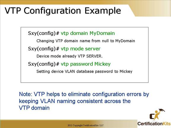
To setup VTP a domain name needs to be configured and be the same on all switches throughout the domain. At least one switch needs to be configured in server mode and have all VLANS defined on it. Optionally a password can be configured within the VTP domain for additional security.
To communicate VLAN information between switches, the following must occur:
1. The VTP management domain name of both switches must be set the same
2. At least one of the switches must be configured as a VTP server
3. Other switches that you wish to dynamically learn the VLANs should be configured in vtp client mode
4. No router is necessary
Cisco CCNA VTP Revisions
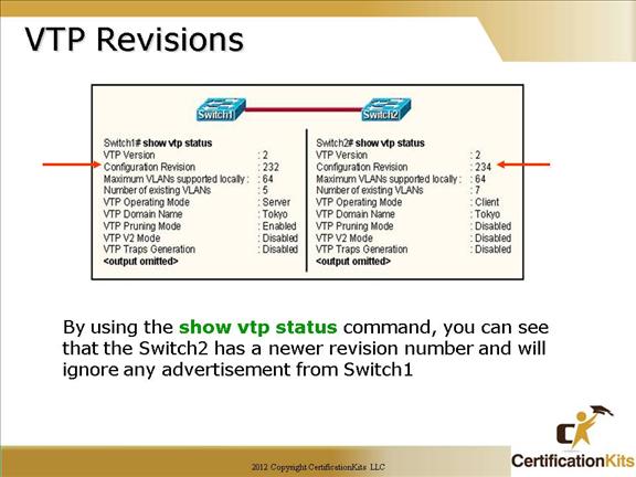
Note: The VTP revision number is important in that if a new switch is placed on the network in Server mode and has a higher revision number than the current switch in Server mode, all clients will start learning the VLANs defined on the new switch and delete the valid VLANs learned by the original switch configured as a VTP Server.
Cisco CCNA VTP Physical Design Example
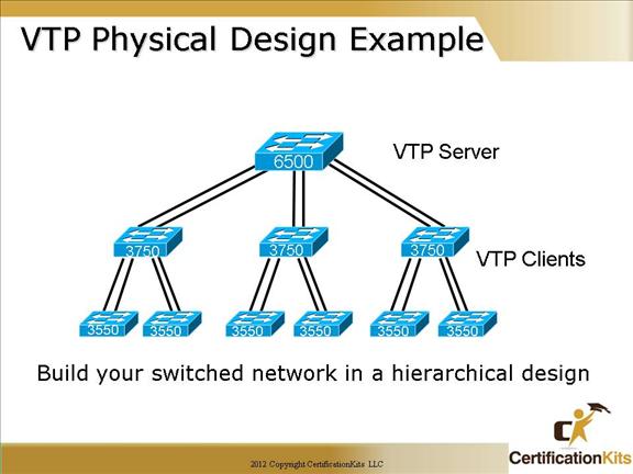
Typically from a design perspective, the main core switch is configured as the VTP Server and all other switches as VTP clients. This works well is you have hundreds of VLANs. If you just have a handful of VLANs, configuring all switches in transparent mode and manually creating the VLANs required on the respective switches works well also.
Cisco CCNA Show commands for VLAN’s
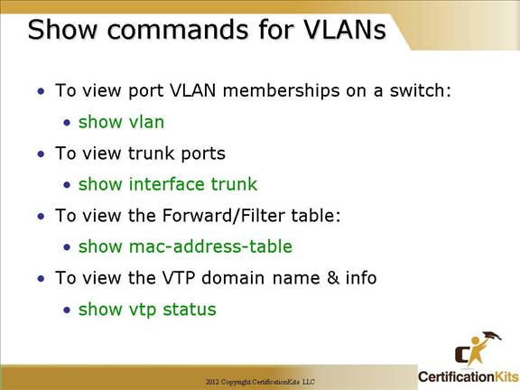
You must remember these commands!!
show vlan – Displays VLAN memberships on a switch
show interface trunk – Displays port and module interface trunk information
show mac-address-table – Displays the Forward/Filter (MAC address) table
show vtp status – Displays the VTP statistics and domain information
Cisco CCNA Gathering information to Configure Switch 2
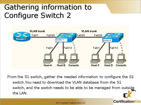
From Switch 1, gather the needed information to configure Switch 2.
switch1>enable
switch1#show vtp status
Write down the vtp domain name (case sensitive)
switch1#show running-config
Write down the ip address, mask and default gateway
1. Login to switch 2 and configure the next IP address in the range under the VLAN 1 interface (don’t forget to do a “no shut”)
2. Set the ip default-gateway for the switch
3. Set the VTP domain name
4. Set the VTP mode to client