Cisco CCNA 802.11 Topology Building Blocks
Following is a summary of the different WLAN topologies:
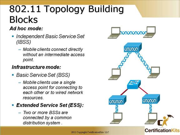
Ad hoc mode: This mode is called Independent Basic Service Set (IBSS). Mobile clients connect directly without an intermediate access point. Operating systems such as Windows have made this peer-to-peer network easy to set up. This setup can be used for a small office (or home office) to allow a laptop to be connected to the main PC or for several people to simply share files. The coverage is limited. Everyone must be able to hear everyone else. An access point is not required. A problem is that peer-to-peer networks are difficult to secure.
Infrastructure mode: In infrastructure mode, where clients connect through an access point, there are two modes:
– Basic Service Set (BSS): The communication devices that create a BSS are mobile clients using a single access point for connectivity to each other or to wired network resources. This should not be confused with the Basic Service Set Identifier (BSSID) which is only the layer 2 MAC address of the BSS access point’s radio card. While the BSS is the single building block for wireless topology and the BSS access point is uniquely identified through a BSSID, the wireless network itself is advertised through a Service Set Identifier (SSID). The SSID is a wireless network name that is user configurable. The SSID can be made up of as many as 32 case sensitive characters to announce the availability of the wireless network to mobile clients.
– Extended Services Set (ESS): The wireless topology is extended with two or more Basic Service Sets connected by a distribution system (DS) or commonly a wired infrastructure. An ESS generally includes a common SSID to allow roaming from access point to access point without requiring client configuration.
These are the original standard define 802.11 topologies while other topologies such as repeaters, bridges, and work group bridges are vendor specific extensions.
Cisco CCNA BSA Wireless Topology—Basic Coverage
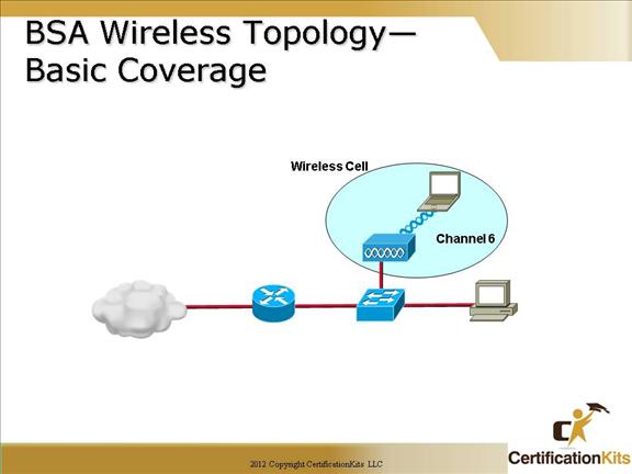
The physical area of radio frequency (RF) coverage provided by an access point in a BSS is known as the basic service area (BSA). This area can is dependant on the RF created with variations caused by access point power output, antenna type, and physical surroundings effecting the RF. While the BSS is the topology building block and the BSA is the actual coverage pattern, there terminology usage are commonly interchangeable for basic wireless discussions.
The access point attaches to the Ethernet backbone and communicates with all the wireless devices in the cell area. The access point is the master for the cell and controls traffic flow to and from the network. The remote devices do not communicate directly with each other; they communicate with the access point. The access point is user configurable with it’s unique RF channel and wireless SSID name.
The access point broadcasts the name of the wireless cell in the SSID through beacons. Beacons are broadcasts that the access points send to announce the available services. It is used to logically separate WLANs. It must match exactly between the client and the access point. However clients can be configured without an SSID (null-SSID), detect all access points, and learn the SSID from the beacons of the access point. A common example of the discovery process is used by the integrated Windows Zero Configuration (WZC) utility when using a wireless laptop at a new location. The user is simply displayed the newly found wireless service and ask to connect or supply appropriate keying material to join. SSID broadcasts can be disabled on the access point but this approach does not work if the client needs to see the SSID in the beacon.
Cisco CCNA ESA Wireless Topology— Extended Cover
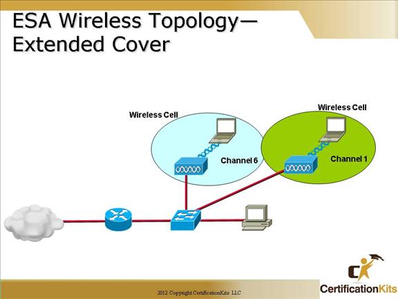
If a single cell does not provide enough coverage, any number of cells can be added to extend the range. This range is known as an extended service area (ESA).
It is recommended that the ESA cells have 10 to 15 percent overlap to allow remote users to roam without losing RF connections. For wireless voice networks, an overlap of 15 to 20 percent is recommended. Bordering cells should be set to different non-overlapping channels for best performance.
Cisco CCNA Wireless Topology Data Rates—802.11b
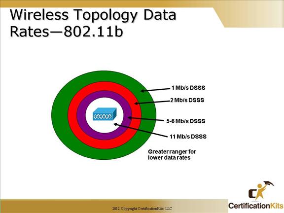
WLAN clients have the ability to shift data rates while moving. This technique allows the same client operating at 11 Mbps to shift to 5.5 Mbps, 2 Mbps, and finally still communicate in the outside ring at 1 Mbps. This rate shifting happens without losing the connection and without any interaction from the user. Rate shifting also happens on a transmission-by-transmission basis; therefore, the access point has the ability to support multiple clients at multiple speeds depending upon the location of each client.
– Higher data rates require stronger signals at the receiver. Therefore, lower data rates have a greater range.
– Wireless clients always try to communicate with the highest possible data rate.
– The client will reduce the data rate only if transmission errors and transmission retries occur.
This approach provides the highest total throughput within the wireless cell. The above visual is for 802.11b, however the same concept applies to 802.11a or 802.11g data rates.
Cisco CCNA Access Point Configuration
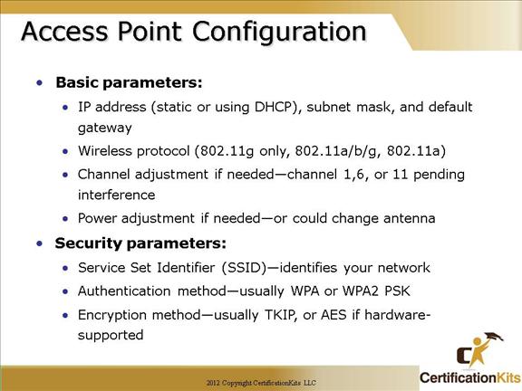
Wireless access points can be configured through a command line interface or more commonly a browser GUI. However, the mode of configuration the basic wireless parameters are the same. Basic wireless access point parameters are SSID, RF channel with optional power, and authentication (security) while wireless client basic parameters only include authentication. Wireless clients need less parameters since the wireless NIC will scan all available RF it’s capable of (meaning an 802.11b/g card can not scan 5 GHz) to locate the RF channel and will usually initiate the connection with a null-SSID to discover the SSIDs available. Therefore by 802.11 design if using open authentication, the result is plug-n-play. When security is configured with Pre-Shared Keys (PSK) for older WEP or current WPA, remember they must be an exact match to allow connectivity.
Depending on the hardware chosen for the access point, it might be capable of both frequencies of 2.4 GHz ISM band and 5 GHz UNII band and all three IEEE 802.11a/b/g implementations. This result will usually allow for fine adjustment of which frequencies to offer through which radio to enable and which IEEE standard to use on that RF. While the details of this related to items such as 802.11b/g Mode versus 802.11g Mode only are not applicable for this course, a basic summary should be observed. When 802.11b wireless clients are mixed with 802.11g wireless clients, the resulting throughput decreases since the access point must start implemented a protection RTS/CTS protocol. Hence if you simply to only one IEEE wireless client type, throughput will be greater than in a mixed mode.
After configuring the basic required wireless parameters of the access point, additional fundamental wired side parameters must be configured for default router and DHCP server. Given a pre-existing LAN, there must be a default router to exit the network and a DHCP server to lease IP addresses to wired PCs. The access point simply uses the existing router and DHCP servers for relaying IP address to wireless clients. Since the network has been expanded, verify the existing DHCP IP address scope is large enough to accommodate the new wireless client additions. If this is a new installation with all router and access point functions in the same hardware, then you simple configure all parameter in the same hardware.
Cisco CCNA Steps to Implement a Wireless Network
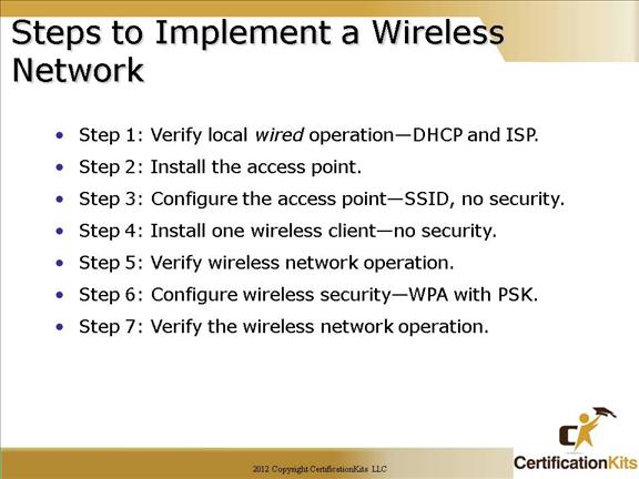
The basic approach to wireless implementation (as with any basic networking) is to gradually configure and test incrementally.
Before any wireless, verify pre-exiting network and internet access for the wired hosts. Then implement wireless with only a single access point and single client without wireless security. Verify the wireless client receives a DHCP IP address and can ping the local wired default router and then browse to the external Internet. Lastly, configure wireless security with WPA. Only use WEP if hardware equipment is too old to support WPA.
Cisco CCNA Common Wireless Network Issues
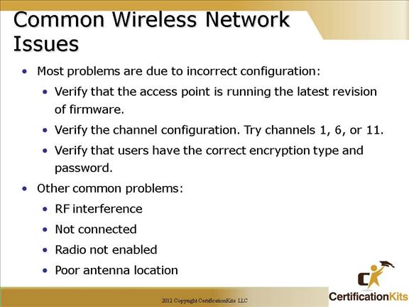
If you follow the prior stated steps for implementing wireless network, the divide and conquer technique via incremental configuration will most likely lead to most likely cause. Most common configuration issues are :
-Configuring a defined SSID on the client (versus it’s discovery method of SSID) that does not match access point (inclusive of case sensitivity).
-Configuring incompatible security methods. Both wireless client and access point must match for authentication method (EAP or PSK) and encryption method (TKIP or AES).
Other common problems resulting from initial RF installation:
– Is the radio enabled on both the access point and client for the correct RF (2.4 GHz ISM or 5 GHz UNII)?
– Is an external antenna connected and facing correct direction (straight upward for dipole)?
– Is the antenna location too high or too low relative to wireless clients (within 20 vertical feet)?
-Metal object in the room reflecting RF and causing poor performance ?
-Attempting to reach too great of a distance capable ?