CCNP SWITCH Analyzing Campus Network Designs
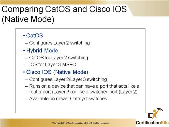
So how do you know which commands to use on each switch? Well, the more familiar you become with the different operating systems, the more it make sense. There essentially are two main operating systems usually referred to as the “Set Based” switch and the “IOS Based” switch. We will explore both of them throughout this course.
CCNP SWITCH Switching Benefits
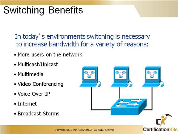
In non-switched flat topology networks of today, when one PC wants to talk to another every PC hears and tries to process the communication to decide if they are the destination.
This is bad because:
The CPU on every PC must Process the data frames.
Collisions of data occur more frequently.
As more users use the network less bandwidth is available.
High bandwidth applications suck up the available bandwidth.
In a switched network, switches learn the MAC addresses of every device attached to each port. Once the mac address is learned, the switch can now forward the frames from the source interface directly to the port of the destination interface. This virtually eliminates collisions, eliminates broadcast storms and frees valuable bandwidth.
CCNP SWITCH Benefits Of Layer 3 Devices
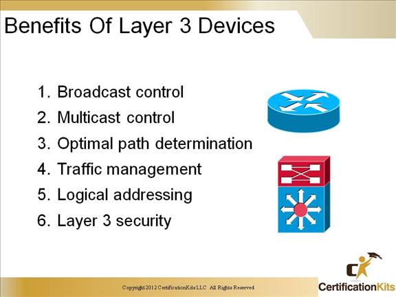
Ok, we are already familiar with Routing and the benefits of routing so why are we mentioning it here in a switching module? Well because routing will always play an important part in all networking functionality. Within this switching course we will identify that some switches have built in or modular routing functionality. The hardware platforms that do not have built in or modular routing functionality still have a default gateway. It is that default gateway, the router, that completes the building blocks of a network.
CCNP SWITCH Customer Network Requirements
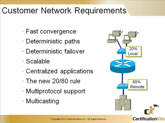
When we combine the benefits of switching and routing we achieve the following:
- • Fast convergence
- • Deterministic paths
- • Deterministic failover
- • Scalable
- • Centralized applications
- • The new 20/80 rule (Traffic is 20% Local and 80% Remote)
- • Multiprotocol support
- • Multicasting
CCNP SWITCH Emerging Campus Structure
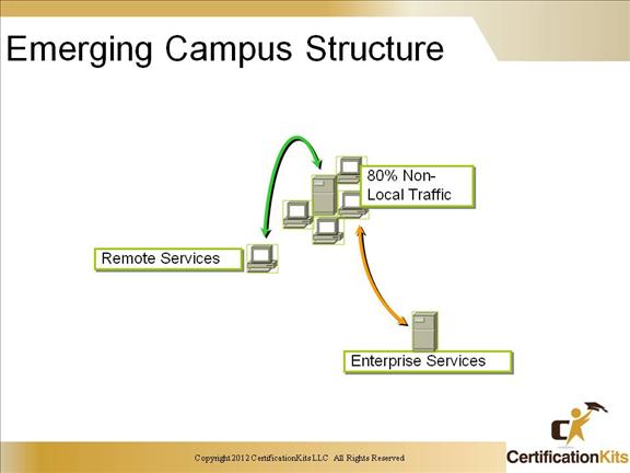
Local Services
- • Layer 2 devices connected by switches
- • Traffic within the same subnet/VLAN/Color
- • Traffic does not cross the backbone
Remote Services
- • Devices connected by routers
- • Traffic crosses subnet/VLAN
- • Traffic may/may not cross the backbone
Enterprise Services
- • Common to all users
- • Traffic crosses subnet/VLAN
- • Traffic must cross backbone
- • Segregated by Layer 3
- • May be grouped by Layer 2
CCNP SWITCH The Hierarchical Model
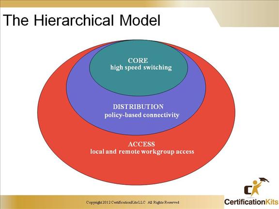
Cisco recommends that we build our networks with some logic behind our placement of each device. Cisco’s Hierarchical Module consists of 3 separate layers; Core, Distribution and Access layer. The Access Layer of the network is the point at where end-users are allowed into the network. The key function of this layer is to provide access for end-users into the network. In the campus environment, some of the functions performed by this layer are as follows:
Shared bandwidth
Switched bandwidth
Layer 2 services, such as VLAN membership and traffic filtering based on broadcast or MAC addresses.
The Distribution layer is located between the Access and Core Layer. It provides a boundary definition and designates where potentially “expensive” or processor intensive packet manipulations such as filtering are handled.
The functions are represented in the Distribution Layer are as follows:
Broadcast or multicast domain definition.
InterVLAN routing
Media translations
Security
Filtering and policy based connectivity.
The sole purpose of the Core Layer of the network is to move traffic as fast as possible. This layer of the network should not be involved in time consuming packet manipulation or any processing that slows down the traffic switching. Functions such as access lists and packet filtering should be avoided in the Core Layer.
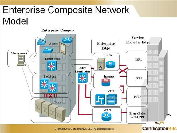
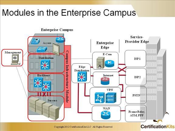
CCNP SWITCH Enterprise Composite Network Model
CCNP SWITCH Modules in the Enterprise Campus
CCNP SWITCH Campus Infrastructure Module
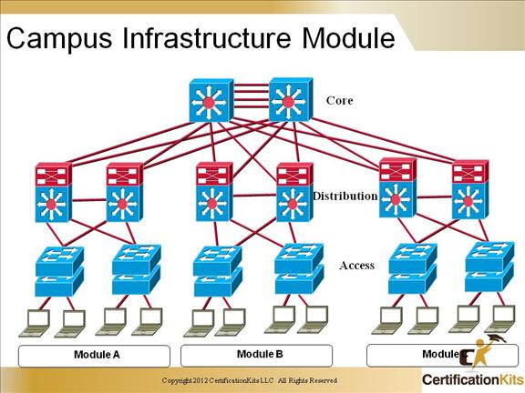
The Cisco three layer model network model with a Core, Distribution and Access Layer is a typical model for larger campus networks. Having redundant connections within and between layers aids with designing and robust network.
CCNP SWITCH A Collapsed Core
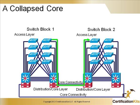
A collapsed core might sound like a bad situation, but its not! A collapsed core is a term used to identify that you are using a device that operates in the Distribution layer and also in the Core layer. This is when the Core layer gets “shoved” up into the Distribution layer.
CCNP SWITCH Increasing FE Performance with Full Duplex
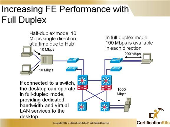
There are a number of different types of mediums that you can choose to use in your network. The deciding factor on what type of medium you use will depend mainly on the type of medium that switch supports. Fastethernet standards allow your medium to operate 10times faster than 10Mbps and operating in fullduplex your medium can offer up to 200Mbps thoughput, but it doesn’t stop there. Can you say gigabit. Gigabit speeds enhances client/server performance across the enterprise and is used mainly to connect distribution-layer switches in each building with a central campus core. Here is a quick peek at the different characteristics each type of switching medium covered in this section.
Standard Cable Mode Pairs Distance
10BaseT 3,4,5 Half 2 100
100BaseTX 5 Half/Full 2 100
100BaseT4 3 Half 4 100
100BaseT2 3,4,5 Half/Full 2 100
100BaseFX multimode Half/Full 1 400/half 2000/full
100BaseFX Singlemode Half/Full 1 10 km
GIG Standard Cable Size BW Distance
1000BaseSX 62.5um 160 200
1000BaseSX 62.5 200 275
1000BaseSX 50 400 500
1000BaseSX 50 500 550
1000BaseLX 62.5 500 550
1000BaseLX 50 400 550