Cisco CCNP SWITCH Implementing Inter-VLAN Routing
Cisco CCNP SWITCH Router on a Stick
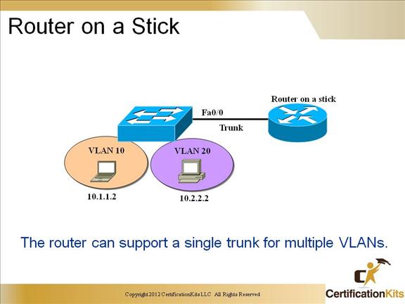
The Inter-Switch Link (ISL) is a Cisco proprietary trunking protocol used to inter-connect two VLAN-capable devices connected at Fast Ethernet or higher. The ISL protocol is a packet-tagging protocol that contains a standard Ethernet frame and the VLAN information associated with that frame. Since ISL is a trunking protocol, it can carry traffic from multiple VLANs.
Advantages:
Simple to implement using any combination of systems
Router provides communications between VLANs on remote switches
Disadvantages:
Single point of failure if only one router is used
Single traffic path can become congested
Network topology can cause performance issues
Cisco CCNP SWITCH Router on a Stick Between VLANs with ISL Trunks
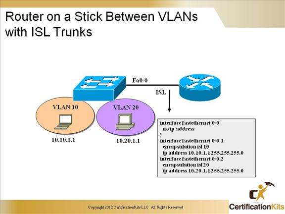
When utilizing ISL trunks on a router, sub-interfaces are utilized on fastethernet and higher interfaces. ISL trunks are Cisco Proprietary.
Cisco CCNP SWITCH Router on a Stick Between VLANs with 802.1Q Trunks
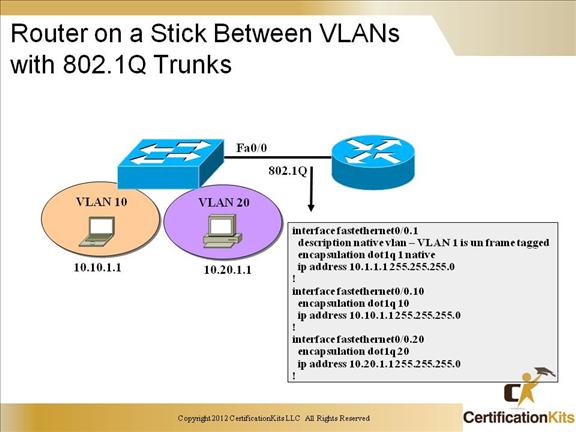
When utilizing 802.1Q trunks, otherwise known as dot1q trunks, sub-interfaces are utilized on fastethernet and higher interfaces. Dot1q trunks are standards based so they can interoperate with equipment other than just Cisco equipment.
Cisco CCNP SWITCH Layer 3 Switching Components
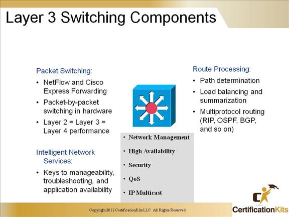
This slide poses the problem of communicating between VLANs. VLANs, by their nature, are designed to keep data from traversing the VLAN borders.
End users stations need to communicate with entities outside the VLAN borders. Hardware Layer 3 switching allows the Policy Feature Card (PFC) and Distributed Forwarding Cards (DFCs), instead of the Multi-Layer Switch Feature Card (MSFC), to forward IP unicast traffic between subnets. Hardware Layer 3 switching provides wire-speed forwarding on the PFC and DFCs, instead of in software on the MSFC.
Hardware Layer 3 switching requires minimal support from the MSFC. The MSFC routes any traffic that cannot be hardware Layer 3 switched. Hardware Layer 3 switching supports the routing protocols configured on the MSFC. Hardware Layer 3 switching does not replace the routing protocols configured on the MSFC. Hardware Layer 3 switching runs equally on the PFC and DFCs to provide IP unicast Layer 3 switching locally on each module.
Hardware Layer 3 switching provides the following functions:
• Hardware access control list (ACL) switching for policy-based routing (PBR)
• H/W NetFlow switching for TCP intercept, reflexive ACL forwarding decisions
• H/W Cisco Express Forwarding (CEF) switching for all other IP unicast traffic
Cisco CCNP SWITCH IP Unicast Frame and Packet Rewrite
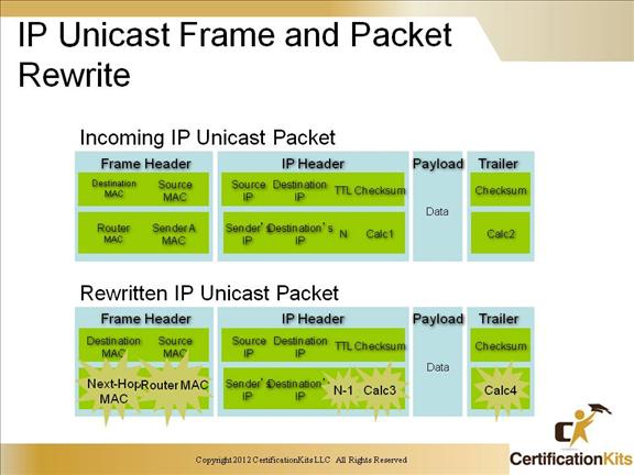
When a packet is Layer 3 switched from a source in one subnet to a destination in another subnet, the Catalyst 6500 series switch performs a packet rewrite at the egress port based on information learned from the MSFC so that the packets appear to have been routed by the MSFC.
Packet rewrite alters five fields:
• Layer 2 (MAC) destination address
• Layer 2 (MAC) source address
• Layer 3 IP Time to Live (TTL)
• Layer 3 checksum
• Layer 2 (MAC) checksum (also called the frame checksum or FCS)
Cisco CCNP SWITCH Processor Switching versus ASIC Switching
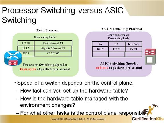
Route processor and ASIC in the multilayer forwarding engine work together. Cisco identifies the routing process as being handled by the RP (Routing Processor) and the switching function being handled by the SE (Switching Engine).
Cisco CCNP SWITCH Topology-Based Switching
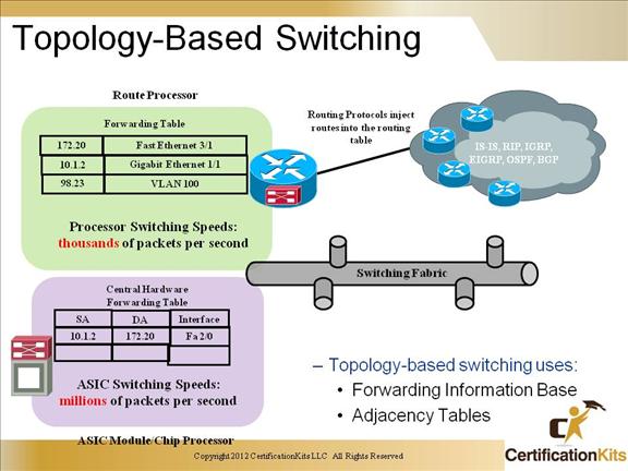
Topology-based switching uses:
- • Forwarding Information Base
- • Adjacency Tables
Cisco CCNP SWITCH ARP Throttling
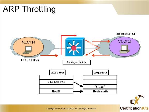
ARP throttling limits the rate at which packets destined to a connected network are forwarded to the route processor. Most of these packets are dropped, but a small number are sent to the router (rate limited).
Cisco CCNP SWITCH Troubleshooting CEF
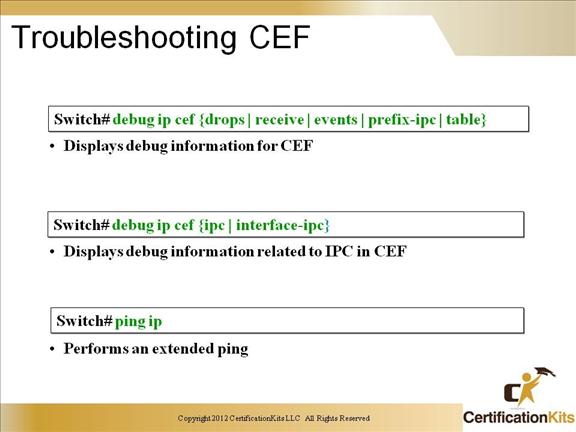
Cisco’s Express Forwarding (CEF) technology for IP is a scalable, distributed, layer 3 switching solution designed to meet the future performance requirements of the Internet and Enterprise networks. It represents the latest advance in Cisco IOSTM switching capabilities that includes NetFlowTM Switching and Distributed Switching. CEF is also a key component of Cisco’s Tag Switching architecture.
Cisco CCNP SWITCH Switching & Routing Ports
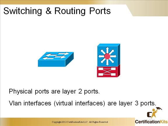
Layer 2-only interfaces associated with a physical port. Access ports carry the traffic of and belongs to only one VLAN. Trunk ports carry the traffic of multiple VLANs. By default is a member of all VLANs in the VLAN database. Configure switch ports using the switchport interface configuration commands.
Layer 3 switch virtual interfaces represent a VLAN of switch ports as one interface to the routing or bridging function in the system. L3 interfaces are created the first time that you enter the vlan interface configuration command for a VLAN interface. You would configure a VLAN interface for each VLAN for which you want to route traffic, and assign it an IP address.
Cisco CCNP SWITCH Routed Ports
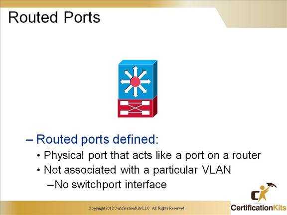
To configure a routed port:
- Enable IP routing within the switch.
- Put the interface into Layer 3 mode with the no switchport interface configuration command.
- Assign an IP address and subnet mask to the port.
- Assign routing protocol characteristics by enabling IP routing.
Cisco CCNP SWITCH Isolated Broadcast Domains
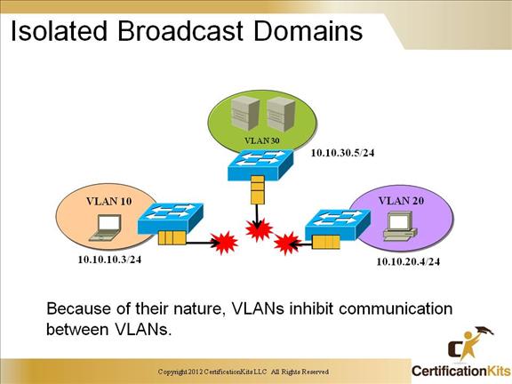
VLANs, by their nature, are designed to keep data from traversing the VLAN borders. However, end users stations need to communicate with entities outside the VLAN borders.
Cisco CCNP SWITCH Solution: Routing Between VLANs
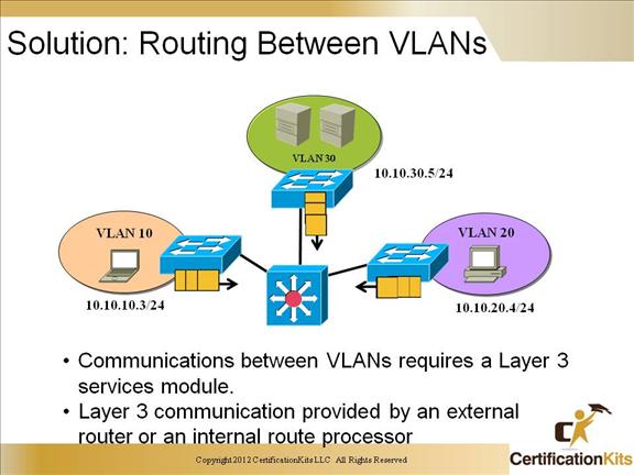
In switched networks, route processors are used to provide communications between VLANs. Before you can configure routing between VLANs, you must have defined the VLANs on the switches in your network.
Cisco CCNP SWITCH Configuring Inter-VLAN Routing on a Switch
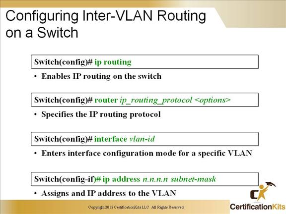
A majority of today’s switches can be configured as either layer 2 or layer 3. To enable a Cisco switch to be capable of layer 3 routing, the ip routing command is utilized. When switchports are utilized, ip addresses are configured on the interface vlan.
Cisco CCNP SWITCH Verifying Inter-VLAN Routing
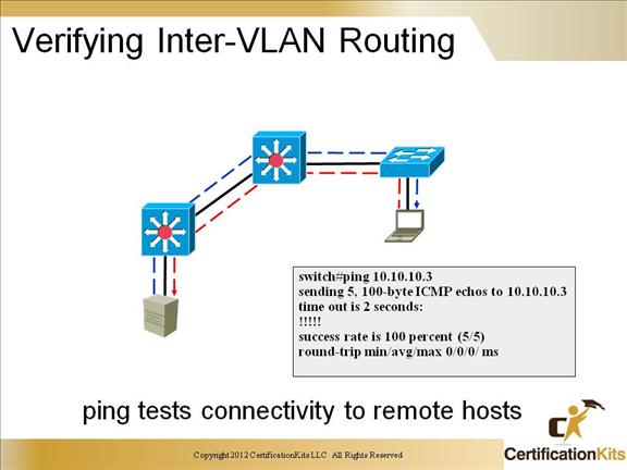
Use the ping command to test connectivity to remote hosts. The ping command will return one of the following responses:
Success rate is 100 percent or ip address is alive. This response occurs in 1 to 10 seconds, depending on network traffic and the number of ICMP packets sent.
Destination does not respond. No answer message is returned if the host does not
Unknown host. This response occurs if the targeted host does not exit
Destination unreachable. This response occurs if the default gateway cannot reach the specified network
Network or host unreachable. This response occurs if there is no entry in the route table for the host or network.
You can also test the routes packets will take from the route processor to a specific destination by using the trace ip destination command.
Cisco CCNP SWITCH Verifying Inter-VLAN Routing
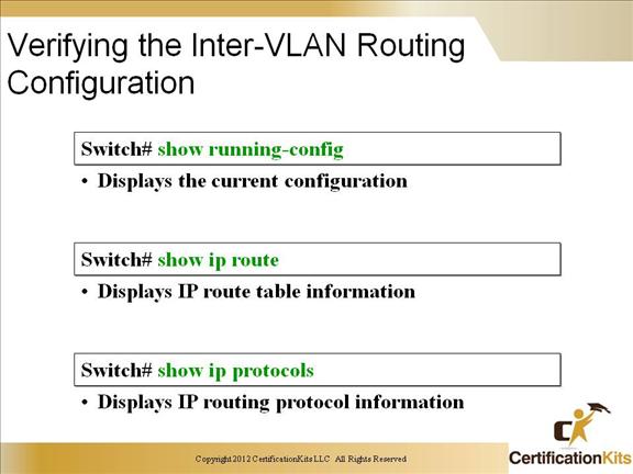
The above slide lists three valuable show commands that can be used to verify layer three configuration.
Cisco CCNP SWITCH Centralized Forwarding
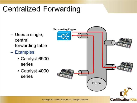
Centralized forwarding architecture-The supervisor’s (Cisco Express Forwarding) engine performs all forwarding decisions; optional distributed forwarding is supported as an upgrade
Forwarding performance-Forwards up to 30 mpps per system (Cisco Express Forwarding) or when equipped with the optional dCEF daughter card for full local forwarding, can deliver up to 48 mpps sustained throughput per slot with sustained system throughput of up to 400 mpps
Cisco CCNP SWITCH Distributed Forwarding
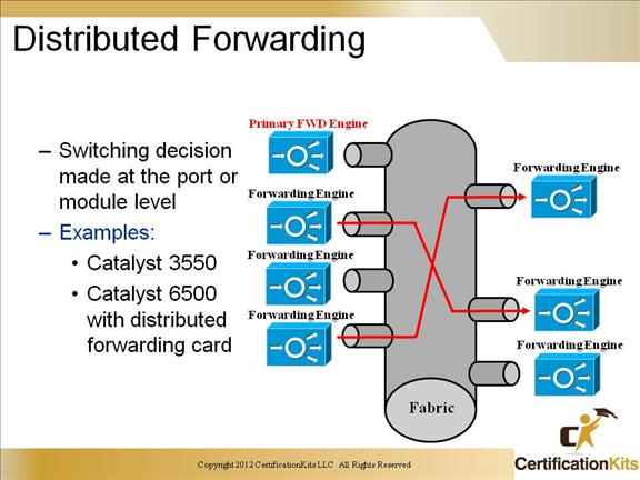
The Catalyst 6500 Distributed Forwarding Card is installed in DFC-enabled line-card modules that perform distributed forwarding supported by the Catalyst 6500 Supervisor Engine 2 as a field upgrade. These line cards include the WS-X6516-GBIC and the WS-X6816-GBIC.
Key Features:
When the Distributed Forwarding Card is installed, Line cards that are DFC-enabled make forwarding decisions locally, leaving the supervisor engine free to perform routing and management functions
The Distributed Forwarding Card supports Cisco’s distributed Cisco Express Forwarding (CEF)-based forwarding architecture
The Distributed Forwarding Card replicates Layer 2 and 3 forwarding logic in hardware as well as a bus on each line card