Cisco CCNP SWITCH Implementing Spanning Tree
Cisco CCNP SWITCH Redundant Topology
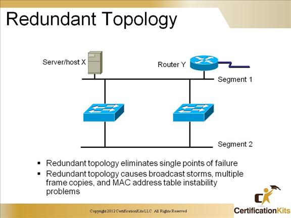
Spanning Tree Protocol is a bridge protocol that enables a learning bridge to dynamically work around loops in a network topology by creating a spanning tree. Bridges exchange Bridge Protocol Data Unit (BPDU) messages with other bridges to detect loops, and then remove the loops by shutting down selected bridge interfaces.
Spanning Tree Protocol is a standardized technique for maintaining a network of multiple bridges or switches. When the topology changes, Spanning Tree Protocol transparently reconfigures bridges and switches to avoid the creation of loops by placing ports in a forwarding or blocking state. Each VLAN is treated as a separate bridge and a separate instance of Spanning Tree Protocol is applied to each. Spanning Tree Protocol parameters are set for each VLAN. For each spanning tree instance, you configure a set of global options with a set of port parameters. The port parameter list contains only ports that are members of a given VLAN. A maximum of 64 spanning tree instances are supported, one for each VLAN.
STP provides a loop free redundant network topology by placing certain ports in the blocking state. STP uses the Spanning Tree Algorithm (STA) to find redundant links and shut them down. STP’s main task is to stop network loops from occurring on your layer-2 network (bridges or switches). It vigilantly monitors the network to find all links, making sure that no loops occur by shutting down any redundant ones.
Cisco CCNP SWITCH Spanning-Tree Operations
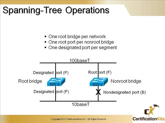
A switch performs spanning tree by default. The default settings will elect a root bridge and calculate the shortest path from every switch to the root
Cisco CCNP SWITCH STP Port States
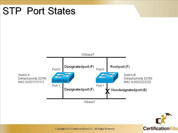
Active Ports will have the lowest combination of:
Root Path Cost
Bridge ID (of upstream bridge)
Port ID
Path from any switch to the root will travel either directly to the root bridge or though a parent or “designated” switch. Blocked ports continue to send/receive BPDUs but NOT DATA.
Cisco CCNP SWITCH Spanning-Tree
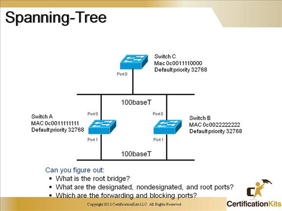
Switch C will become the Root Bridge because it has the lowest Bridge ID. Port 0 on Switch A and Port 0 on Switch B will become the Root Port, Port 1 on switch A will become the designated port because the port has a lower port ID.
Cisco CCNP SWITCH STP State Transitions
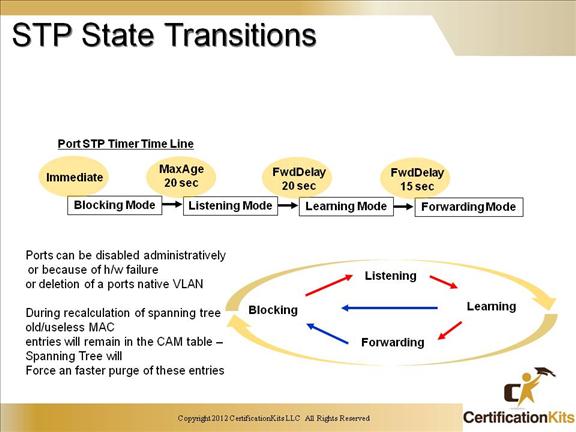
Disabled = Administratively Down
Blocking = Receiving BPDUs
Listening = Sending and Receiving BPDUs (building the topology)
Learning = Populating CAM table
Forwarding = Sending/Receiving User Data
Cisco CCNP SWITCH Calculating Root Path Cost
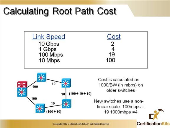
Path cost is a function of bandwidth of each path. It can be changed using a switch port cost parameter. Is determined by the sum of port costs between source and destination.
Cisco CCNP SWITCH BPDU Timers
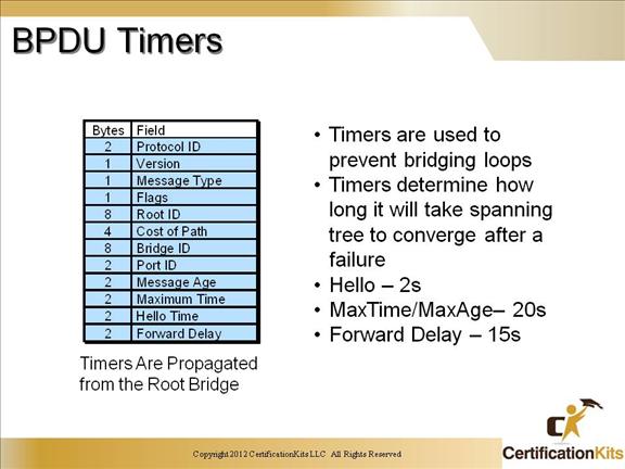
BPDU timers are set by the Root bridge. By default the hello interval is set to once every 2 seconds. Why so often? To avoid loops!
Cisco CCNP SWITCH PVST
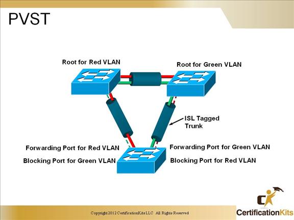
Per VLAN Spanning Tree allows the network administrator to control the forwarding paths on per vlan basis. It also creates a flexible design tool for traffic management that will give you the capability to provide layer 2 redundancy.
Cisco CCNP SWITCH Enabling Spanning Tree
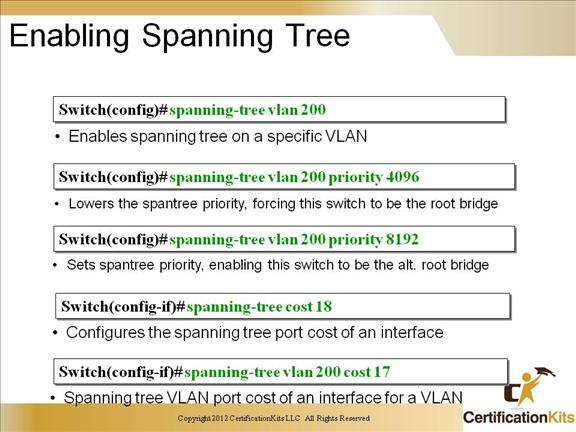
Wow, the whole enchilada. We placed a bullet point under each of the commands to help you digest what is going on in these examples. All of the above is not necessary to configure spanning-tree, but it shows the flexibility in dictating which switch will become the root bridge.
Cisco CCNP SWITCH Verifying STP
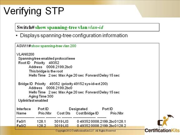
To display information for the specified spanning-tree instances, use the show spanning-tree command in privileged EXEC mode.
The keywords and arguments that are available with the show spanning-tree command will vary depending on the platform you are using and the network modules that are installed and operational. The example on the slide shows the “vlan” argument being utilized.