In preparation of your CCNA exam, we want to make sure we cover the various concepts that we could see on your Cisco CCNA exam. So to assist you, below we provided one of our CCNA Labs, the Four Router IS-IS Lab. As you progress through your CCNA exam studies, I am sure you will find that hands on experience you receive from such as lab will go a long way in helping you acheive your Cisco certification!
Equipment Needed (per POD):
- 1 router with 1 serials ports and 1Ethernet port
- 1 router with 2 serial ports and 1 Ethernet port
- 1 router with 3 serial ports
- Cisco IOS 10.0. or higher
- 4 DTE/DCE serial crossover cables
- 1 crossover cable (Ethernet to Ethernet)
- 1 PC running a terminal emulation program
- 1 roll over cable for console port access
Router Configuration:
- Erase the startup-config on all routers
- Reload the routers
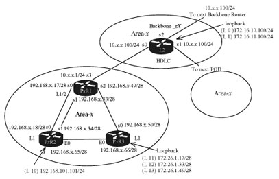
PxRx (the first x represents the POD number and the second x represents the router number. Example: To indicate router 1 in POD 1 we type PxR1) Shut down the interface S3 on router1 going to the Border Router. The area number is your POD number. The following is an example of the configuration for the routers in POD1. All pertinent commands are in bold.
P1R1
router>en
router#config t
router(config)#hostname P1R1
P1R1(config)#int s0
P1R1(config-if)#ip address 192.168.1.17 255.255.255.240
P1R1(config-if)#clockrate 64000
P1R1(config-if)#description Connection to P1R2 Serial 0
P1R1(config-if)#no shut
P1R1(config-if)#int s1
P1R1(config-if)#ip address 192.168.1.33 255.255.255.240
P1R1(config-if)#clockrate 64000
P1R1(config-if)#description Connection to P1R2 Serial 1
P1R1(config-if)#no shut
P1R1(config-if)#int s2
P1R1(config-if)#ip address 192.168.1.49 255.255.255.240
P1R1(config-if)#clockrate 64000
P1R1(config-if)#description Connection to P1R3 Serial 0
P1R1(config-if)#no shut
P1R1(config-if)#int s3
P1R1(config-if)#ip address 10.1.1.1 255.255.255.0
P1R1(config-if)#clockrate 64000
P1R1(config-if)#description Connection to Backbone Router S0
P1R1(config-if)#no shut
P1R2
router>en
router#config t
router(config)#hostname P1R2
P1R2(config)#int e0
P1R2(config-if)#ip address 192.168.1.65 255.255.255.240
P1R2(config-if)#description Ethernet connection to E0 P1R3
P1R2(config-if)#no shut
P1R2(config-if)#int s0
P1R2(config-if)#ip address 192.168.1.18 255.255.255.240
P1R2(config-if)#description Connection to P1R1 Serial 0
P1R2(config-if)#no shut
P1R2(config-if)#int s1
P1R2(config-if)#ip address 192.168.1.33 255.255.255.240
P1R2(config-if)#description Connection to P1R2 Serial 1
P1R2(config-if)#no shut
P1R2(config)#int loopback 10
P1R2(config-if)#ip address 192.168.101.101 255.255.255.0
P1R2(config-if)#description Used for testing purposes
P1R2(config-if)#no shut
P1R3
router>en
router#config t
P1R3(config)#int e0
P1R3(config-if)#ip address 192.168.1.66 255.255.255.240
P1R3(config-if)#description Ethernet connection to P1R2 E0
P1R3(config-if)#no shut
P1R3(config-if)#int s0
P1R3(config-if)#ip address 192.168.1.50 255.255.255.240
P1R3(config-if)#description Connection to P1R1 Serial 2
P1R3(config-if)#no shut
P1R3(config)#int loopback 11
P1R3(config-if)#ip address 172.26.1.17 255.255.255.240
P1R3(config-if)#description Used for testing purposes
P1R3(config-if)#no shut
P1R3(config-if)#int loopback 12
P1R3(config-if)#ip address 172.26.1.33 255.255.255.240
P1R3(config-if)#description Used for testing purposes
P1R3(config-if)#no shut
P1R3(config-if)#int loopback 13
P1R3(config-if)#ip address 172.26.1.49 255.255.255.240
P1R3(config-if)#description Used for testing purposes
P1R3(config-if)#no shut
Backbone_R1
router>en
router#config t
router(config)#hostname Backbone_R1
Backbone_R1(config)#int s0
Backbone_R1(config-if)#ip address 10.1.1.100 255.255.255.0
Backbone_R1(config-if)#description Connection to P1R1 Serial 3
Backbone_R1(config-if)#no shut
Backbone_R1(config)#int loopback 0
Backbone_R1(config-if)#ip address 172.16.10.100 255.255.255.0
Backbone_R1(config-if)#description Used for testing purposes
Backbone_R1(config-if)#no shut
Backbone_R1(config-if)#int loopback 1
Backbone_R1(config-if)#ip address 172.16.11.100 255.255.255.0
Backbone_R1(config-if)#description Used for testing purposes
Backbone_R1(config-if)#no shut
Enabling IS-IS within your POD
Enable IS-IS on the PxR1, PxR2 and PxR3 routers within your POD.
Configure the PxR1, PxR2 and PxR3 routers within your POD with the IS-IS NETs shown in the following table:
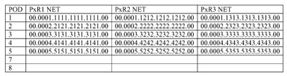
This following is an example of configuring IS-IS on the router in POD 1.
P1R1>en
P1R1#config t
P1R1(config)#router isis
P1R1(config-router)#net 00.0001.1111.1111.1111.00
P1R2>en
P1R2#config t
P1R2(config)#router isis
P1R2(config-router)#net 00.0001.1212.1212.1212.00
P1R3>en
P1R3#config t
P1R3(config)#router isis
P1R3(config-router)#net 00.0001.1313.1313.1313.00
Configure the backbone router with a NET of 00.0013.1111.2222.3333.00
Backbone_R1>en
Backbone_R1#config t
Backbone_R1(config)#router isis
Backbone_R1(config-router)#net 00.0013.1111.2222.3333.00
Enable IS-IS on the interfaces specified in the following table on the PxR1, PxR2 and PxR3 routers within your POD an on the Backbone_Rx router.
Important! For this part of the lab, you’ll need to disable the S3 interface on PxR1 that connects to the Backbone_Rx.
P1R1>en
P1R1#config t
P1R1(config)#int s3
P1R1(config-if)#shut
The following is an example on how to enable IS-IS on a router’s interface. This example is for POD 1 routers.
P1R1(config)#int s0
P1R1(config-if)#ip router isis
P1R1(config-if)#int s1
P1R1(config-if)#ip router isis
P1R1(config-if)#int s2
P1R1(config-if)#ip router isis
P1R1(config)#int s3
P1R1(config-if)#ip router isis
P1R1(config-if)#exit
P1R2(config)#int s0
P1R2(config-if)#ip router isis
P1R2(config-if)#int s1
P1R2(config-if)#ip router isis
P1R2(config-if)#int e0
P1R2(config-if)#ip router isis
P1R2(config-if)#int loopback 10
P1R2(config-if)#ip router isis
P1R2(config-if)#exit
P1R2(config)#
P1R3(config)#int s0
P1R3(config-if)#ip router isis
P1R3(config-if)#int e0
P1R3(config-if)#ip router isis
P1R3(config-if)#int loopback 11
P1R3(config-if)#ip router isis
P1R3(config-if)#int loopback 12
P1R3(config-if)#ip router isis
P1R3(config-if)#int loopback 13
P1R3(config-if)#ip router isis
P1R3(config-if)#exit
P1R3(config)#
Display the routing table of the PxR1, PxR2 and PxR3 routers within your POD and verify that you have full connectivity within your POD.
The following example output is from the P1R1.
P1R1#sh ip route
(Output omitted)
Gateway of last resort is not set
172.16.0.0/28 is subnetted, 3 subnets
i L1 172.16.1.48
i L1 172.16.1.32 [115/20] via 192.168.1.50, Serial2
i L1 172.16.1.16 [115/20] via 192.168.1.50, Serial2
192.168.1.0/28 is subnetted, 4 subnets
i L1 192.168.1.64 [115/20] via 192.168.1.18, Serial0
C 192.168.1.32 is directly connected, Serial1
C 192.168.1.48 is directly connected, Serial2
C 192.168.1.16 is directly connected, Serial0
i L1 192.168.101.0/24 [115/20] via 192.168.1.18, Serial0
P1R1#
This output shows that there is full connectivity to all three routers in POD 1.
Does IS-IS load balance by default? __________
What is the IS-IS routing metric based on by default?
Use the show clns int s0 command to determine the Level 1 and Level 2 default metric.
P1R1#sh clns int s0
Serial0 is up, line protocol is up
Checksums enabled, MTU 1500, Encapsulation HDLC
ERPDUs enabled, min. interval 10 msec.
CLNS fast switching enabled
CLNS SSE switching disabled
DEC compatibility mode OFF for this interface
Next ESH/ISH in 38 seconds
Routing Protocol: IS-IS
Circuit Type: level-1-2
Interface number 0x0, local circuit ID 0x100
Neighbor System-ID: P1R2
Level-1 Metric: 10, Priority: 64, Circuit ID: P1R2.00
Number of active level-1 adjacencies: 1
Level-2 Metric: 10, Priority: 64, Circuit ID: P1R1.00
Number of active level-2 adjacencies: 1
Next IS-IS Hello in 3 seconds
P1R1#
What is the Level 1 and Level 2 default metric for IS-IS? ______
What is the default administrative distance of IS-IS routes? ______
P1R1#sh ip protocols
Routing Protocol is “isis”
Invalid after 0 seconds, hold down 0, flushed after 0
Outgoing update filter list for all interfaces is not set
Incoming update filter list for all interfaces is not set
Redistributing: isis
Address Summarization:
None
Maximum path: 4
Routing for Networks:
Serial0
Serial1
Serial2
Routing Information Sources:
Gateway Distance Last Update
192.168.1.33 115 00:17:58
192.168.1.50 115 00:16:13
192.168.101.101 115 00:13:10
192.168.1.18 115 00:18:32
172.16.1.17 115 00:13:10
Distance: (default is 115)
Save the current configuration on all POD routers
Enabling Connectivity to the Backbone_Rx router
Important! On PxR1, re-enable the S3 interface by using the no shut command.
P1R1(config)#int s3
P1R1(config-if)#no shut
P1R1(config-if)#
03:10:07: %LINK-3-UPDOWN: Interface Serial3, changed state to up
Next, enable IS-IS routing on the S0, loopback 0, and loopback 1 interface on the Backbone_Rx router.
Backbone_R1#config t
Backbone_R1(config)#int s0
Backbone_R1(config-if)#ip router isis
Backbone_R1(config-if)#int loopback 0
Backbone_R1(config-if)#ip router isis
Backbone_R1(config-if)#loopback 1
Backbone_R1(config-if)#int loopback 1
Backbone_R1(config-if)#ip router isis
Backbone_R1(config-if)#exit
Backbone_R1(config)#
Do show ip route on all three routers in your POD to ensure you have connectivity with the Backbone_Rx router.
P1R1#sh ip route
(Output omitted)
Gateway of last resort is not set
172.16.0.0/24 is subnetted, 2 subnets
i L2 172.16.10.0 [115/20] via 10.1.1.100, Serial3
i L2 172.16.11.0 [115/20] via 10.1.1.100, Serial3
172.26.0.0/28 is subnetted, 3 subnets
i L1 172.26.1.48 [115/20] via 192.168.1.50, Serial2
i L1 172.26.1.32 [115/20] via 192.168.1.50, Serial2
i L1 172.26.1.16 [115/20] via 192.168.1.50, Serial2
10.0.0.0/24 is subnetted, 1 subnets
C 10.1.1.0 is directly connected, Serial3
192.168.1.0/28 is subnetted, 4 subnets
i L1 192.168.1.64 [115/20] via 192.168.1.18, Serial0
C 192.168.1.32 is directly connected, Serial1
C 192.168.1.48 is directly connected, Serial2
C 192.168.1.16 is directly connected, Serial0
i L1 192.168.101.0/24 [115/20] via 192.168.1.18, Serial0
P1R1#
Do you see the loopback interfaces for the Backbone_Rx router and along with the other routers in your POD? _______
Does IS_IS perform autosumarization across the network boundary by default? ________
Does IS-IS use the same administrative distance for Level 1 and Level 2 routes? _______
Make sure you can ping the loopback interfaces on the Backbone_Rx router from all routers with in your POD.
Save the current configuration to NVRAM.
Changing the IS-IS Router Type
What command can be used to determine the IS-IS router type? ___________________
P1R1#sh clns is-neighbors
| System | IdInterface | State | Type Priority | Circuit Id |
| Format | ||||
| P1R2 | Se1 | Up | IS 0 | 00 |
| Phase V | ||||
| P1R2 | Se0 | Up | L1L2 0 /0 | 00 |
| Phase V | ||||
| P1R3 | Se2 | Up | L1L2 0 /0 | 00 |
| Phase V | ||||
| Backbone_R1 | Se3 | Up | L2 0 | 00 |
| Phase V | ||||
| P1R1# |
Examine the IS-IS link-state database of the three POD routers. Do you see both the Level 1 and Level 2 link-state database on all routers? The following is an example of the link-state database on P1R1.
P1R1#sh is database
IS-IS Level-1 Link State Database:
| LSPID | LSP Seq Num | LSP Checksum | LSP Holdtime |
| ATT/P/OL | |||
| P1R1.00-00 | * 0x00000015 | 0x424A | 672 |
| 1/0/0 | |||
| P1R2.00-00 | 0x00000014 | 0x4F4C | 749 |
| 1/0/0 | |||
| P1R3.00-00 | 0x00000018 | 0x47DF | 758 |
| 1/0/0 |
IS-IS Level-2 Link State Database:
| LSPID | LSP Seq Num | LSP Checksum | LSP Holdtime |
| ATT/P/OL | |||
| P1R1.00-00 | * 0x00000021 | 0x8384 | 890 |
| 0/0/0 | |||
| Backbone_R1.00-00 | 0x00000012 | 0x7E10 | 742 |
| 0/0/0 | |||
| P1R2.00-00 | 0x0000001D | 0x2C06 | 788 |
| 0/0/0 | |||
| P1R3.00-00 | 0x0000001B | 0xA8E9 | 743 |
| 0/0/0 | |||
| P1R1# |
The LSPs with an Asterisk are the local LSPs. Those are LSPs that originated from the router.
Configure the PxR2 and PxR3 routers within your POD to be Level 1 IS-IS routers.
P1R2(config)#router isis
P1R2(config-router)#is-type level-1
P1R3(config)#router isis
P1R3(config-router)#is-type level-1
What is the advantages of configuring the PxR2 and PxR3 routers within the POD to be Level 1
IS-IS routers?
Re-examine the link-state database of the PxR2 and PxR3 within your POD. Do the routers
contain only the level 1 link-state database now? _____________
P1R2#sh isis database
IS-IS Level-1 Link State Database:
| LSPID | LSP Seq Num | LSP Checksum | LSP Holdtime |
| ATT/P/OL | |||
| P1R1.00-00 | 0x0000001A | 0x384F | 950 |
| 1/0/0 | |||
| P1R2.00-00 | * 0x00000016 | 0x4162 | 853 |
| 0/0/0 | |||
| P1R3.00-00 | 0x0000001B | 0x37F6 | 948 |
| 0/0/0 | |||
| P1R2# |
Re-examine the routing table on the PxR2 and PxR3 routers. What are the differences now that they have become Level 1 routers?
P1R2#sh ip route
(Output omitted)
Gateway of last resort is 192.168.1.17 to network 0.0.0.0
172.26.0.0/28 is subnetted, 3 subnets
i L1 172.26.1.48 [115/30] via 192.168.1.17, Serial0
i L1 172.26.1.32 [115/30] via 192.168.1.17, Serial0
i L1 172.26.1.16 [115/30] via 192.168.1.17, Serial0
10.0.0.0/24 is subnetted, 1 subnets
i L1 10.1.1.0 [115/20] via 192.168.1.17, Serial0
192.168.1.0/28 is subnetted, 4 subnets
C 192.168.1.64 is directly connected, Ethernet0
C 192.168.1.32 is directly connected, Serial1
i L1 192.168.1.48 [115/20] via 192.168.1.17, Serial0
C 192.168.1.16 is directly connected, Serial0
C 192.168.101.0/24 is directly connected, Loopback10
i*L1 0.0.0.0/0 [115/10] via 192.168.1.17, Serial0
In the PxR2 and PxR3 routing tables, do you see a default route through the PxR1 router?
Try and ping the loopback interfaces on the Backbone_Rx router from the PxR2 and PxR3 routers. This will tell you if the default route is working.
Save the current configuration of all routers within your POD to NVRAM.
Configure Route summarization
Display the routing table on the Backbone_Rx router. Do you see your 192.168.x.x/28 and 172.26.x.x subnets?
Backbone_R1#sh ip route
(Output omitted)
Gateway of last resort is not set
172.16.0.0/24 is subnetted, 2 subnets
C 172.16.10.0 is directly connected, Loopback0
C 172.16.11.0 is directly connected, Loopback1
172.26.0.0/28 is subnetted, 3 subnets
i L2 172.26.1.48 [115/30] via 10.1.1.1, Serial0
i L2 172.26.1.32 [115/30] via 10.1.1.1, Serial0
i L2 172.26.1.16 [115/30] via 10.1.1.1, Serial0
10.0.0.0/24 is subnetted, 1 subnets
C 10.1.1.0 is directly connected, Serial0
192.168.1.0/28 is subnetted, 4 subnets
i L2 192.168.1.64 [115/30] via 10.1.1.1, Serial0
i L2 192.168.1.32 [115/20] via 10.1.1.1, Serial0
i L2 192.168.1.48 [115/20] via 10.1.1.1, Serial0
i L2 192.168.1.16 [115/20] via 10.1.1.1, Serial0
i L2 192.168.101.0/24 [115/30] via 10.1.1.1, Serial0
Backbone_R1#
Configure the level 1-2 router within your POSD to perform route summarization. Summarize the 192.168.x.x/28 and the 172.16.x.x/28 subnets within your POD to 192.168.x.0/24 and 172.16.x.0/24 (where x is your POD number).
The following shows how to configure the P1R1 router, the Level 1-2 router in POD1.
P1R1(config)#router isis
P1R1(config-router)#summary-address 192.168.1.0 255.255.255.0
P1R1(config-router)#summary-address 172.16.1.0 255.255.255.0
Re-examine the routing table of the Backbone_Rx router: so you see the summarized routes?
Backbone_R1#sh ip route
(Output omitted)
Gateway of last resort is not set
172.16.0.0/24 is subnetted, 2 subnets
C 172.16.10.0 is directly connected, Loopback0
C 172.16.11.0 is directly connected, Loopback1
172.26.0.0/24 is subnetted, 1 subnets
i L2 172.26.1.0 [115/30] via 10.1.1.1, Serial0
10.0.0.0/24 is subnetted, 1 subnets
C 10.1.1.0 is directly connected, Serial0
i L2 192.168.1.0/24 [115/20] via 10.1.1.1, Serial0
i L2 192.168.101.0/24 [115/30] via 10.1.1.1, Serial0
Backbone_R1#
From the Backbone_Rx try and ping all the interface within your POD.
Were you successful? ___________
Save the current configuration to NVRAM.
Using IS-IS show and debug commands.
At the PxR2 router, enable the debug isis adj-packets command and observe the output.
P1R2#debug isis adj-packets
IS-IS Adjacency related packets debugging is on
P1R2#
06:21:14: ISIS-Adj: Sending L1 LAN IIH on Loopback10, length 1514
06:21:17: ISIS-Adj: Sending serial IIH on Serial0, length 1499
06:21:17: ISIS-Adj: Sending L1 LAN IIH on Ethernet0, length 1497
06:21:18: ISIS-Adj: Rec serial IIH from *HDLC* (Serial0), cir type
L1L2, cir id
00, length 1499
00, length 1499
06:21:18: ISIS-Adj: Action = ACCEPT
06:21:18: ISIS-Adj: Sending serial IIH on Serial1, length 1499
06:21:20: ISIS-Adj: Rec serial IIH from *HDLC* (Serial1), cir type
L1L2, cir id
What type of hello packet is PxR2 sending tp PxR3 over the Ethernet interface?
________________
Disable debugging on PxR2 router.
P1R2#no debug all
All possible debugging has been turned off
P1R2#
On PxR2, enter the show clns int e0 command. What is the default IS-IS priority set to?
P1R2#sh clns int e0
Ethernet0 is up, line protocol is up
Checksums enabled, MTU 1497, Encapsulation SAP
ERPDUs enabled, min. interval 10 msec.
CLNS fast switching enabled
CLNS SSE switching disabled
DEC compatibility mode OFF for this interface
Next ESH/ISH in 16 seconds
Routing Protocol: IS-IS
Circuit Type: level-1-2
Interface number 0x2, local circuit ID 0x1
Level-1 Metric: 10, Priority: 64, Circuit ID: P1R2.01
Number of active level-1 adjacencies: 0
Next IS-IS LAN Level-1 Hello in 1 seconds
P1R2#
On PxR2 change the E0 interface IS-IS priority to 63.
P1R2#config t
P1R2(config)#int e0
P1R2(config-if)#isis priority 63
Using the show clns int e0 command again on PxR2, verify that the DR has now changed to the other router.
P1R2# sh clns int e0
Ethernet0 is up, line protocol is up
Checksums enabled, MTU 1497, Encapsulation SAP
ERPDUs enabled, min. interval 10 msec.
CLNS fast switching enabled
CLNS SSE switching disabled
DEC compatibility mode OFF for this interface
Next ESH/ISH in 45 seconds
Routing Protocol: IS-IS
Circuit Type: level-1-2
Interface number 0x2, local circuit ID 0x1
Level-1 Metric: 10, Priority: 63, Circuit ID: P1R3.01
Number of active level-1 adjacencies: 1
Next IS-IS LAN Level-1 Hello in 3 seconds
At the PxR2 router enable the debug isis update-packets command. Shut and then no shut the e0 interface on the PxR2 router and observe the debug output.
P1R2#debug isis update-packets
IS-IS Update related packet debugging is on
P1R2#
09:21:08: ISIS-Upd: Rec L1 LSP 1313.1313.1313.00-00, seq 31, ht 1197,
09:21:08: ISIS-Upd: from SNPA *HDLC* (Serial0)
09:21:08: ISIS-Upd: LSP newer than database copy
09:21:08: ISIS-Upd: TLV contents different, code 128
09:21:08: ISIS-Upd: TLV contents different, code 2
09:21:08: ISIS-Upd: Full SPF required
09:21:08: ISIS-Upd: Sending L1 LSP 1313.1313.1313.00-00, seq 31, ht
1195 on Ethernet0
09:21:17: ISIS-Upd: Building L1 LSP
09:21:17: ISIS-Upd: TLV contents different, code 2
09:21:17: ISIS-Upd: Full SPF required
09:21:17: ISIS-Upd: Sending L1 LSP 1212.1212.1212.00-00, seq 30, ht
1199 on Serial0
09:21:30: ISIS-Upd: Building L1 LSP
09:21:30: ISIS-Upd: TLV contents different, code 2
09:21:30: ISIS-Upd: Full SPF required
09:21:30: ISIS-Upd: Sending L1 LSP 1212.1212.1212.00-00, seq 31, ht
1199 on
Disable the debug on PxR2.
P1R2#no debug all All possible debugging has been turned off
P1R2#
01:03:50 8 3 1 PERIODIC
00:48:49 8 3 1 PERIODIC
00:33:47 8 3 1 PERIODIC
00:18:46 8 3 1 PERIODIC
00:12:50 16 4 4 P1R2.00-00 NEWADJ NEWLSP
TLVCONTENT
00:06:21 16 4 1 P1R3.00-00 TLVCONTENT
00:06:16 8 3 1 P1R2.00-00 TLVCONTENT
00:06:04 16 4 3 P1R2.00-00 NEWADJ TLVCONTENT
00:03:46 12 4 1 PERIODIC
P1R2#
At the PxR2 router, use the proper show command to examine the IS-IS neighbor table. How many entries do you see? Are they all Level 1?
P1R2#show clns is-neighbors
| System Id | Interface | State | Type Priority | Circuit Id |
| Format | ||||
| P1R1 | Se0 | Up | L1 0 | 00 |
| Phase V | ||||
| P1R1 | Se1 | Up | IS 0 | 00 |
| Phase V | ||||
| P1R3 | Et0 | Up | L1 64 | P1R3.01 |
| Phase V | ||||
| P1R2# |
Copy your current configuration to NVRAM.
I hope you found this article to be of use and it helps you prepare for your Cisco CCNA certification. Achieving your CCNA certification is much more than just memorizing Cisco exam material. It is having the real world knowledge to configure your Cisco equipment and be able to methodically troubleshoot Cisco issues. So I encourage you to continue in your studies for your CCNA exam certification.