In preparation of your CCNA exam, we want to make sure we cover the various concepts that we could see on your Cisco CCNA exam. So to assist you, below we will discuss the foundation of the CCNA exam; Cisco TCP/IP. As you progress through your CCNA exam studies, I am sure with repetition you will find this topic becomes easier. So even though it may be a difficult concept and confusing at first, keep at it as no one said getting your Cisco certification would be easy!
Introduction
In the two decades since their invention, the heterogeneity of networks has expanded further with the deployment of Ethernet, Token Ring, Fiber Distributed Data Interface (FDDI), X.25, Frame Relay, Switched Multimegabit Data Service (SMDS), Integrated Services Digital Network (ISDN), and most recently, Asynchronous Transfer Mode (ATM). The Internet protocols are the best proven approach to internetworking this diverse range of LAN and WAN technologies.
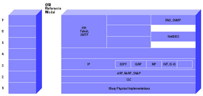
The Internet Protocol suite includes not only lower-level specifications, such as Transmission Control Protocol (TCP) and Internet Protocol (IP), but specifications for such common applications as electronic mail, terminal emulation, and file transfer. Figure 1 shows the TCP/IP protocol suite in relation to the OSI Reference model. Figure 2 shows some of the important Internet protocols and their relationship to the OSI Reference Model. For information on the OSI Reference model and the role of each layer, please refer to the document Internetworking Basics.
The Internet protocols are the most widely implemented multivendor protocol suite in use today. Support for at least part of the Internet Protocol suite is available from virtually every computer vendor.
TCP/IP Technology
This section describes technical aspects of TCP, IP, related protocols, and the environments in which these protocols operate. Because the primary focus of this document is routing (a layer 3 function), the discussion of TCP (a layer 4 protocol) will be relatively brief.
TCP
TCP is a connection-oriented transport protocol that sends data as an unstructured stream of bytes. By using sequence numbers and acknowledgment messages, TCP can provide a sending node with delivery information about packets transmitted to a destination node. Where data has been lost in transit from source to destination, TCP can retransmit the data until either a timeout condition is reached or until successful delivery has been achieved. TCP can also recognize duplicate messages and will discard them appropriately. If the sending computer is transmitting too fast for the receiving computer, TCP can employ flow control mechanisms to slow data transfer. TCP can also communicates delivery information to the upper-layer protocols and applications it supports. All these characteristics makes TCP an end-to-end reliable transport protocol. TCP is specified in RFC 793 .
Figure 1 TCP/IP Protocol Suite in Relation to the OSI Reference Model
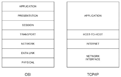
Figure 2 Important Internet Protocols in Relation to the OSI Reference Model
Refer to the TCP section of Internet Protocols for more information.
IP
IP is the primary Layer 3 protocol in the Internet suite. In addition to internetwork routing, IP provides error reporting and fragmentation and reassembly of information units called datagrams for transmission over networks with different maximum data unit sizes. IP represents the heart of the Internet Protocol suite.
Note: The term IP in the section refers to IPv4 unless otherwise stated explicitly.
IP addresses are globally unique, 32-bit numbers assigned by the Network Information Center. Globally unique addresses permit IP networks anywhere in the world to communicate with each other.
An IP address is divided into two parts. The first part designates the network address while the second part designates the host address.
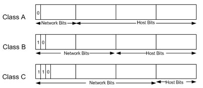
The IP address space is divided into different network classes. Class A networks are intended mainly for use with a few very large networks, because they provide only 8 bits for the network address field. Class B networks allocate 16 bits, and Class C networks allocate 24 bits for the network address field. Class C networks only provide 8 bits for the host field, however, so the number of hosts per network may be a limiting factor. In all three cases, the left most bit(s) indicate the network class. IP addresses are written in dotted decimal format; for example, 34.0.0.1. Figure 3 shows the address formats for Class A, B, and C IP networks.
Figure 3 Address Formats for Class A, B, and C IP Networks
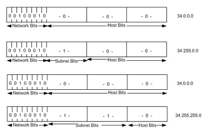
IP networks also can be divided into smaller units called subnetworks or “subnets.” Subnets provide extra flexibility for the network administrator. For example, assume that a network has been assigned a Class A address and all the nodes on the network use a Class A address. Further assume that the dotted decimal representation of this network's address is 34.0.0.0. (All zeros in the host field of an address specify the entire network.) The administrator can subdivide the network using subnetting. This is done by “borrowing” bits from the host portion of the address and using them as a subnet field, as depicted in Figure 4.
Figure 4 “Borrowing” Bits
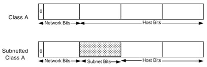
If the network administrator has chosen to use 8 bits of subnetting, the second octet of a Class A IP address provides the subnet number. In our example, address 34.1.0.0 refers to network 34, subnet 1; address 34.2.0.0 refers to network 34, subnet 2, and so on.
The number of bits that can be borrowed for the subnet address varies. To specify how many bits are used to represent the network and the subnet portion of the address, IP provides subnet masks. Subnet masks use the same format and representation technique as IP addresses. Subnet masks have ones in all bits except those that specify the host field. For example, the subnet mask that specifies 8 bits of subnetting for Class A address 34.0.0.0 is 255.255.0.0. The subnet mask that specifies 16 bits of subnetting for Class A address 34.0.0.0 is 255.255.255.0. Both of these subnet masks are pictured in Figure 5. Subnet masks can be passed through a network on demand so that new nodes can learn how many bits of subnetting are being used on their network.
Figure 5 Subnet Masks
Traditionally, all subnets of the same network number used the same subnet mask. In other words, a network manager would choose an eight-bit mask for all subnets in the network. This strategy is easy to manage for both network administrators and routing protocols. However, this practice wastes address space in some networks. Some subnets have many hosts and some have only a few, but each consumes an entire subnet number. Serial lines are the most extreme example, because each has only two hosts that can be connected via a serial line subnet.
As IP subnets have grown, administrators have looked for ways to use their address space more efficiently. One of the techniques that has resulted is called Variable Length Subnet Masks (VLSM). With VLSM, a network administrator can use a long mask on networks with few hosts and a short mask on subnets with many hosts. However, this technique is more complex than making them all one size, and addresses must be assigned carefully.
Of course in order to use VLSM, a network administrator must use a routing protocol that supports it. Cisco routers support VLSM with Open Shortest Path First (OSPF), Integrated Intermediate System to Intermediate System (Integrated IS-IS), Enhanced Interior Gateway Routing Protocol (Enhanced IGRP), and static routing. Refer to IP Addressing and Subnetting for New Users for more information about IP addressing and subnetting.
On some media, such as IEEE 802 LANs, IP addresses are dynamically discovered through the use of two other members of the Internet protocol suite: Address Resolution Protocol (ARP) and Reverse Address Resolution Protocol (RARP). ARP uses broadcast messages to determine the hardware (MAC layer) address corresponding to a particular network-layer address. ARP is sufficiently generic to allow use of IP with virtually any type of underlying media access mechanism. RARP uses broadcast messages to determine the network-layer address associated with a particular hardware address. RARP is especially important to diskless nodes, for which network-layer addresses usually are unknown at boot time.
Routing in IP Environments
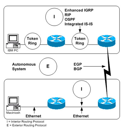
An “internet” is a group of interconnected networks. The Internet, on the other hand, is the collection of networks that permits communication between most research institutions, universities, and many other organizations around the world. Routers within the Internet are organized hierarchically. Some routers are used to move information through one particular group of networks under the same administrative authority and control. (Such an entity is called an autonomous system.) Routers used for information exchange within autonomous systems are called interior routers, and they use a variety of interior gateway protocols (IGPs) to accomplish this end. Routers that move information between autonomous systems are called exterior routers; they use the Exterior Gateway Protocol (EGP) or Border Gateway Protocol (BGP). Figure 6 shows the Internet architecture.
Figure 6 Representation of the Internet Architecture
Routing protocols used with IP are dynamic in nature. Dynamic routing requires the software in the routing devices to calculate routes. Dynamic routing algorithms adapt to changes in the network and automatically select the best routes. In contrast with dynamic routing, static routing calls for routes to be established by the network administrator. Static routes do not change until the network administrator changes them.
IP routing tables consist of destination address/next hop pairs. This sample routing table from a Cisco router shows that the first entry is interpreted as meaning “to get to network 34.1.0.0 (subnet 1 on network 34), the next stop is the node at address 54.34.23.12”:
R6-2500# show ip route
Codes: C – connected, S – static, I – IGRP, R – RIP, M – mobile, B – BGP
D – EIGRP, EX – EIGRP external, O – OSPF, IA – OSPF inter area
N1 – OSPF NSSA external type 1, N2 – OSPF NSSA external type 2
E1 – OSPF external type 1, E2 – OSPF external type 2, E – EGP
i – IS-IS, su – IS-IS summary, L1 – IS-IS level-1, L2 – IS-IS level-2
ia – IS-IS inter area, * – candidate default, U – per-user static route
o – ODR, P – periodic downloaded static route
Gateway of last resort is not set
34.0.0.0/16 is subnetted, 1 subnets
O 34.1.0.0
54.0.0.0/24 is subnetted, 1 subnets
C 54.34.23.0 is directly connected, Serial0
R6-2500#
As we have seen, IP routing specifies that IP datagrams travel through an internetwork one router hop at a time. The entire route is not known at the outset of the journey. Instead, at each stop, the next router hop is determined by matching the destination address within the datagram with an entry in the current node's routing table. Each node's involvement in the routing process consists only of forwarding packets based on internal information. IP does not provide for error reporting back to the source when routing anomalies occur.
This task is left to another Internet protocol the Internet Control Message Protocol (ICMP).
ICMP performs a number of tasks within an IP internetwork. In addition to the principal reason for which it was created (reporting routing failures back to the source), ICMP provides a method for testing node reachability across an internet (the ICMP Echo and Reply messages), a method for increasing routing efficiency (the ICMP Redirect message), a method for informing sources that a datagram has exceeded its allocated time to exist within an internet (the ICMP Time Exceeded message), and other helpful messages. All in all, ICMP is an integral part of any IP implementation, particularly those that run in routers. See the Related Information section of this document for more information on ICMP.
Interior Routing Protocols
Interior Routing Protocols (IGPs) operate within autonomous systems. The following sections provide brief descriptions of several IGPs that are currently popular in TCP/IP networks. For additional information on these protocols, please refer to the links in the Related Information section below.
RIP
A discussion of routing protocols within an IP environment must begin with the Routing Information Protocol (RIP). RIP was developed by Xerox Corporation in the early 1980s for use in Xerox Network Systems (XNS) networks. Today, many PC networks use routing protocols based on RIP.
RIP works well in small environments but has serious limitations when used in larger internetworks. For example, RIP limits the number of router hops between any two hosts in an internet to 16. RIP is also slow to converge, meaning that it takes a relatively long time for network changes to become known to all routers. Finally, RIP determines the best path through an internet by looking only at the number of hops between the two end nodes. This technique ignores differences in line speed, line utilization, and all other metrics, many of which can be important factors in choosing the best path between two nodes. For this reason, many companies with large internetworks are migrating away from RIP to more sophisticated routing protocols.
IGRP
With the creation of the Interior Gateway Routing Protocol (IGRP) in the early 1980s, Cisco Systems was the first company to solve the problems associated with using RIP to route datagrams between interior routers. IGRP determines the best path through an internet by examining the bandwidth and delay of the networks between routers. IGRP converges faster than RIP, thereby avoiding the routing loops caused by disagreement over the next routing hop to be taken. Further, IGRP does not share RIP's hop count limitation. As a result of these and other improvements over RIP, IGRP enabled many large, complex, topologically diverse internetworks to be deployed.
EIGRP
Cisco has enhanced IGRP to handle the increasingly large, mission-critical networks being designed today. This enhanced version of IGRP is called Enhanced IGRP. Enhanced IGRP combines the ease of use of traditional distance vector routing protocols with the fast rerouting capabilities of the newer link state routing protocols.
Enhanced IGRP consumes significantly less bandwidth than IGRP because it is able to limit the exchange of routing information to include only the changed information. In addition, Enhanced IGRP is capable of handling AppleTalk and Novell IPX routing information, as well as IP routing information.
OSPF
OSPF was developed by the Internet Engineering Task Force (IETF) as a replacement for RIP. OSPF is based on work started by John McQuillan in the late 1970s and continued by Radia Perlman and Digital Equipment Corporation (DEC) in the mid-1980s. Every major IP routing vendor supports OSPF.
OSPF is an intradomain, link state, hierarchical routing protocol. OSPF supports hierarchical routing within an autonomous system. Autonomous systems can be divided into routing areas. A routing area is typically a collection of one or more subnets that are closely related. All areas must connect to the backbone area.
OSPF provides fast rerouting and supports variable length subnet masks.
Integrated IS-IS
ISO 10589 (IS-IS) is an intradomain, link state, hierarchical routing protocol used as the DECnet Phase V routing algorithm. It is similar in many ways to OSPF. IS-IS can operate over a variety of subnetworks, including broadcast LANs, WANs, and point-to-point links.
Integrated IS-IS is an implementation of IS-IS for more than just OSI protocols. Today, Integrated IS-IS supports both OSI and IP protocols.
Like all integrated routing protocols, Integrated IS-IS calls for all routers to run a single routing algorithm. Link state advertisements sent by routers running Integrated IS-IS include all destinations running either IP or OSI network-layer protocols. Protocols such as ARP and ICMP for IP and End System-to-Intermediate System (ES-IS) for OSI must still be supported by routers running Integrated IS-IS.
Exterior Routing Protocols
EGPs provide routing between autonomous systems. The two most popular EGPs in the TCP/IP community are discussed in this section.
EGP
The first widespread exterior routing protocol was the Exterior Gateway Protocol. EGP provides dynamic connectivity but assumes that all autonomous systems are connected in a tree topology. This was true in the early Internet but is no longer true.
Although EGP is a dynamic routing protocol, it uses a very simple design. It does not use metrics and therefore cannot make true intelligent routing decisions. EGP routing updates contain network reachability information. In other words, they specify that certain networks are reachable through certain routers. Because of its limitations with regard to today's complex internetworks, EGP is being phased out in favor of routing protocols such as BGP.
BGP
BGP represents an attempt to address the most serious of EGP's problems. Like EGP, BGP is an interdomain routing protocol created for use in the Internet core routers. Unlike EGP, BGP was designed to prevent routing loops in arbitrary topologies and to allow policy-based route selection.
BGP was co-authored by a Cisco founder, and Cisco continues to be very involved in BGP development. The latest revision of BGP, BGP4, was designed to handle the scaling problems of the growing Internet.
Cisco's TCP/IP Implementation
In addition to IP and TCP, the Cisco TCP/IP implementation supports ARP, RARP, ICMP, Proxy ARP (in which the router acts as an ARP server on behalf of another device), Echo, Discard, and Probe (an address resolution protocol developed by Hewlett-Packard Company and used on IEEE 802.3 networks). Cisco routers also can be configured to use the Domain Name System (DNS) when host name-to-address mappings are needed.
IP hosts need to know how to reach a router. There are several ways this can be done:
- Add a static route in the host pointing to a router.
- Run RIP or some other IGP on the host.
- Run the ICMP Router Discovery Protocol (IRDP) in the host.
- Run Proxy ARP on the router.
Cisco routers support all of these methods.
Cisco provides many TCP/IP value-added features that enhance applications availability and reduce the total cost of internetwork ownership. The most important of these features are described in the following section.
Access Restrictions
Most networks have reasonably straightforward access requirements. To address these issues, Cisco implements access lists, a scheme that prevents certain packets from entering or leaving particular networks.
An access list is a sequential list of instructions to either permit or deny access through a router interface based on IP address or other criteria. For example, an access list could be created to deny access to a particular resource from all computers on one network segment but permit access from all other segments. Another access list could be used to permit TCP connections from any host on a local segment to any host in the Internet but to deny all connections from the Internet into the local net except for electronic mail connections to a particular designated mail host. Access lists are extremely flexible, powerful security measures and are available not only for IP, but for many other protocols supported by Cisco routers.
Other access restrictions are provided by the Department of Defense-specified security extensions to IP. Cisco supports both the Basic and the Extended security options as described in RFC 1108 of the IP Security Option (IPSO). Support of both access lists and the IPSO makes Cisco a good choice for networks where security is an issue.
Tunneling
Cisco's TCP/IP implementation includes several schemes that allow foreign protocols to be tunneled through an IP network. Tunneling allows network administrators to extend the size of AppleTalk and Novell IPX networks beyond the size that their native protocols can handle.
IP Multicast
The applications that use the TCP/IP protocol suite continue to evolve. The next set of applications on which a lot of work is being done include those that use video and audio information. Cisco continues to be actively involved with the Internet Engineering Task Force (IETF) in defining standards that will enable network administrators to add audio and video applications to their existing networks. Cisco supports the Protocol Independent Multicast (PIM) standard. In addition, Cisco's implementation provides interoperability with the MBONE, a research multicast backbone that exists today.
IP multicasting (the ability to send IP datagrams to multiple nodes in a logical group) is an important building block for applications such as video. Video teleconferencing, for example, requires the ability to send video information to multiple teleconference sites. If one IP multicast datagram containing video information can be sent to multiple teleconference sites, network bandwidth is saved and time synchronization is closer to optimal.
Suppressing Network Information
In some cases, it may be useful to suppress information about certain networks. Cisco routers provide an extensive set of configuration options that allow an administrator to tailor the exchange of routing information within a particular routing protocol. Both incoming and outgoing information can be controlled using a set of commands designed for this purpose. For example, networks can be excluded from routing advertisements, routing updates can be prevented from reaching certain networks, and other similar actions can be taken.
Administrative Distance
In large networks, some routers and routing protocols are more reliable sources of routing information than others. Cisco IP routing software permits the reliability of information sources to be quantified by the network administrator with the administrative distance metric. When administrative distance is specified, the router can select between sources of routing information based on the reliability of the source. For example, if a router uses both IGRP and RIP, one might set the administrative distances to reflect greater confidence in the IGRP information. The router would then use IGRP information when available. If the source of IGRP information failed, the router automatically would use RIP information as a backup until the IGRP source became available again.
Routing Protocol Redistribution
Translation between two environments using different routing protocols requires that routes generated by one protocol be redistributed into the second routing protocol environment. Route redistribution gives a company the ability to run different routing protocols in workgroups or areas where each is particularly effective. By not restricting customers to using only a single routing protocol, Cisco's route redistribution feature minimizes cost while maximizing technical advantage through diversity.
Cisco permits routing protocol redistribution between any of its supported routing protocols. Static route information can also be redistributed. Further, defaults can be assigned so that one routing protocol can use the same metric for all redistributed routes, thereby simplifying the routing redistribution mechanism.
Serverless Network Support
Cisco pioneered the mechanisms that allow network administrators to build serverless networks. Helper addresses, RARP, and BOOTP allow network administrators to place servers far away from the workstations that depend on them, thereby easing network design constraints.
Network Monitoring and Debugging
With today's complex, diverse network topologies, a router's ability to aid the monitoring and debugging process is critical. As the junction point for multiple segments, a router sees more of the complete network than most other devices. Many problems can be detected and/or solved using information that routinely passes through the router.
The Cisco IP routing implementation provides commands that display:
- The current state of the routing table, including the routing protocol that derived the route, the reliability of the source, the next IP address to send to, the router interface to use, whether the network is subnetted, whether the network in question is directly connected, and any routing metrics.
- The current state of the active routing protocol process, including its update interval, metric weights (if applicable), active networks for which the routing process is functioning, and routing information sources.
- The active accounting database, including the number of packets and bytes exchanged between particular sources and destinations.
- The contents of the IP cache, including the destination IP address, the interface through which that destination is reached, the encapsulation method used, and the hardware address found at that destination.
IP-related interface parameters, including whether the interface and interface physical layer hardware are up, whether certain protocols (such as ICMP and Proxy ARP) are enabled, and the current security level.
- IP-related protocol statistics, including the number of packets and number of errors received and sent by the following protocols: IP, TCP, User Datagram Protocol (UDP), EGP, IGRP, Enhanced IGRP, OSPF, IS-IS, ARP, and Probe.
- Logging of all BGP, EGP, ICMP, IGRP, Enhanced IGRP, OSPF, IS-IS, RIP, TCP, and UDP transactions.
- The number of intermediate hops taken as a packet traverses the network.
- Reachability information between nodes.
We hope you found this Cisco certification article helpful. We pride ourselves on not only providing top notch Cisco CCNA exam information, but also providing you with the real world Cisco CCNA skills to advance in your networking career.