In preparation of our CCNA exam, we want to make sure we cover the various concepts that we could see on our Cisco CCNA exam. So to assist you, below we will discuss Configuring Frame Relay.
|
|
||||
|
|
||||
| Configuring Frame Relay | ||||
|
The three commands used to configure basic Frame Relay on a router select the Frame Relay encapsulation type, establish the LMI connection, and enable Inverse ARP: encapsulation frame-relay [cisco | ietf]frame-relay lmi-type {ansi | cisco | q933i} frame-relay inverse-arp [protocol] [dlci] Here’s the procedure for configuring basic Frame Relay: |
||||
| RouterA>enable RouterA#config term RouterA(config)#int ser 1 RouterA(config-if)#address 10.16.0.1 255.255.255.255 RouterA(config-if)#encapsulation frame-relay cisco RouterA(config-if)#frame-relay lmi-type cisco RouterA(config-if)#bandwidth 64 RouterA(config-if)#frame-relay inverse-arp ip 16 RouterA(config-if)#exit RouterA(config)#exit RouterA# |
||||
| Verifying Frame Relay Operations | ||||
| The following commands verify and display Frame Relay information: | ||||
|
||||
| Static Frame Relay Map Configuration | ||||
|
A router’s address-to-DLCI table can be defined statically when inverse ARP is not supported. These static maps can also be used to control broadcasts. To statically configure the map table, use the following command: frame-relay map protocol protocol-address dlci [broadcast][ietf | cisco| payload-compression packet-by-packet] Protocol specifies bridging or logical link control, protocol-address is the network layer and address of the destination device, dlci is the local dlci, broadcast is an optional parameter used to control broadcasts and multicasts over the VC, and payload compression is an optional Cisco proprietary compression method. |
||||
| Frame Relay Topology | ||||
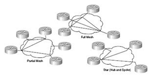
| Frame Relay is a nonbroadcast multi-access (NBMA) connection scheme. This means that although Frame Relay interfaces support multipoint connections by default, broadcast routing updates are not forwarded to remote sites. Frame Relay networks can be designed using star, full-mesh, and partial-mesh topologies. | ||||
| A star topology, also known as a hub-and-spoke configuration, is the common network topology. Remote sites are connected to a central site, which usually provides a service. Star topologies require the fewest PVCs, making them relatively inexpensive. The hub router provides a multipoint connection using a single interface to interconnect multiple PVCs. | ||||
| In a full-mesh topology, all routers have virtual circuits to all other destinations. Although it is expensive, this method provides redundancy, because all sites are connected to all other sites. Full-mesh networks become very expensive as the number of nodes increases. The number of links required in a full-mesh topology with n nodes is (n – (n – 1)) / 2. | ||||
 |
||||
| In a partial-mesh topology, not all sites have direct access to all other sites. Connections usually depend on the traffic patterns within the network. | ||||
| Configuring Frame Relay Summary | ||||
|
||||
| Configuring Frame Relay Subinterfaces | ||||
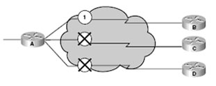
| Frame Relay provides NBMA connectivity between sites, which means that although remote locations can reach each other, routing update broadcasts are not forwarded to all locations. Frame Relay networks use split horizon to prevent routing loops. With split horizon activated, if a remote router receives an update on an interface that has multiple PVCs, the router cannot forward that broadcast to routers on other PVCs on the same interface. | ||||
 |
||||
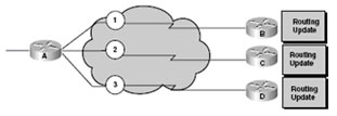
| Routing Update Replication | ||||
| When several DLCIs terminate in a single router, that router must replicate all routing updates and service advertisements on each DLCI. These updates consume bandwidth, cause latency variations, and consume interface buffers, which leads to higher packet rate loss. You should consider broadcast traffic and virtual circuit placement when designing Frame Relay networks to avoid negatively affecting critical user data. | ||||
 |
||||
| Resolving Reachability Issues in Frame Relay | ||||
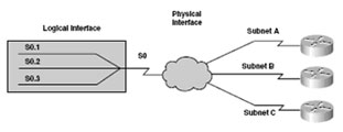
| You can resolve reachability issues by configuring subinterfaces on the router. These logically assigned interfaces allow the router to forward broadcast updates in a Frame Relay network. Subinterfaces are logical subdivisions of a physical interface. Routing updates received on one subinterface can be sent out another subinterface without violating split horizon rules. If you configure virtual circuits as point-to-point connections, the subinterface acts similar to a leased line. | ||||
 |
||||
| Subinterface Configuration | ||||
|
Subinterfaces can be configured as either point-to-point or multipoint. With point-to-point, one PVC connection is established with another physical interface or subinterface on a remote router using a single subinterface. With multipoint, multiple PVC connections are established with multiple physical interfaces or subinterfaces on remote routers on a single subinterface. All interfaces involved use the same subnet, and each interface has its own local DLCI. To configure a subinterface, use the following command: |
||||
|
frame-relay interface-dlci dlci-number To select a subinterface, use the following command: The range of subinterface numbers is to 4294967293. The number that precedes the period (.) must match the physical interface number to which this subinterface belongs. To configure the local DLCI on the subinterface, use the following command: |
||||
| The dlci-number defines the local DLCI number being linked to the subinterface. This is the only way to link an LMI-derived PVC to a subinterface. (LMI does not know about subinterfaces.) | ||||
| Here is the procedure for configuring basic Frame Relay: RouterA>enable RouterA#config term RouterA(config)#int ser0 RouterA(config-if)#no ip address RouterA(config-if)#encapsulation frame-relay cisco RouterA(config-if)#interface serial0.3 point-to-point RouterA(config-if)#frame-relay inverse-dlci 120 RouterA(config-if)#exit RouterA(config)#exit RouterA# |
||||
| The frame-relay inverse-dlci 120 command is required for all point-to-point configurations and multipoint subinterfaces for which Inverse ARP is enabled. Do not use this command on physical interfaces. | ||||
| Configuring Frame Relay Subinterfaces Summary | ||||
|
||||
We hope you found this Cisco certification article helpful. We pride ourselves on not only providing top notch Cisco CCNA exam information, but also providing you with the real world Cisco CCNA skills to advance in your networking career.