In preparation of your CCNA exam, we want to make sure we cover the various concepts that we could see on your Cisco CCNA exam. So to assist you, below we will discuss one of the core CCNA concepts; Configuring VLANs. As you progress through your CCNA exam studies, I am sure with repetition you will find this topic becomes easier. So even though it may be a difficult concept and confusing at first, keep at it as no one said getting your Cisco certification would be easy!
Overview
A VLAN is a switched network that is logically segmented by function, project team, or application, without regard to the physical locations of the users. Any switch port can belong to a VLAN, and unicast, broadcast, and multicast packets are forwarded and flooded only to stations in the VLAN. Each VLAN is considered a logical network, and packets destined for stations that do not belong to the VLAN must be forwarded through a router or bridge as shown in Figure 8-1. VLANs are identified with a number from 1 to 1001.
Because a VLAN is considered a separate logical network, it contains its own bridge Management Information Base (MIB) information and can support its own implementation of the Spanning Tree Protocol (STP).
Figure 8-1 VLANs as Logically Defined Networks
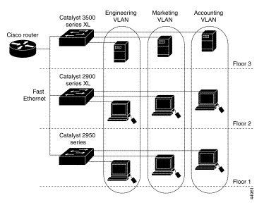
Table 8-1 lists the number of supported VLANs on the switches.
Table 8-1 Maximum Number of Supported VLANs
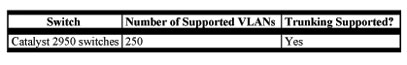
The Catalyst 2950 switches support IEEE 802.1Q trunking methods for transmitting VLAN traffic over 100BASE-T and Gigabit Ethernet ports.
The GigaStack GBIC also supports both trunking methods. When you are configuring a cascaded stack of Catalyst 3500 XL switches that use the GigaStack GBIC and want to include more than one VLAN in the stack, be sure to configure all of the GigaStack GBIC interfaces as trunk ports by using the switchport mode trunk interface configuration command. For more information on these commands, refer to the Catalyst 2950 Desktop Switch Command Reference.
Note The Catalyst 2950 switches do not support ISL trunking.
Trunking is not supported on all switches. For the list of products that support trunking, refer to the release notes.
Management VLANs
Communication with the switch management interfaces is through the switch IP address. The IP address is associated with the management VLAN, which by default is VLAN 1.
The management VLAN has these characteristics:
- It is created from CMS or through the CLI on static-access and dynamic-access and trunk ports. You cannot create or remove the management VLAN through Simple Network Management Protocol (SNMP).
- Only one management VLAN can be administratively active at a time.
- With the exception of VLAN 1, the management VLAN can be deleted.
- When created, the management VLAN is administratively down.
Before changing the management VLAN on your switch network, make sure you follow these guidelines:
- The new management VLAN should not have an Hot Standby Router Protocol (HSRP) standby group configured on it.
- You must be able to move your network management station to a switch port assigned to the same VLAN as the new management VLAN.
- Connectivity through the network must exist from the network management station to all switches involved in the management VLAN change.
- Switches running a IOS software version that is earlier than Cisco IOS 12.0(5)XP cannot have the management VLAN changed.
- Switches running Cisco IOS 12.0(5)XP should be upgraded to the current software release as described in the release notes.
If you are using SNMP or CMS to manage the switch, ensure that the port through which you are connected to a switch is in the management VLAN.
Changing the Management VLAN for a New Switch
If you add a new switch to an existing cluster and the cluster is using a management VLAN other than the default VLAN 1, the command switch automatically senses that the new switch has a different management VLAN and has not been configured. The command switch issues commands to change the management VLAN on the new switch to match the used by the cluster. This automatic change occurs for new, out-of-box switches that do not have a config.text file and for which there have been no changes to the running configuration.
Before a new switch can be added to a cluster, it must be connected to a port that belongs to the cluster management VLAN. If the cluster is configured with a management VLAN other than the default, the command switch changes the management VLAN for new switches when they are connected to the cluster. In this way, the new switch can exchange Cisco Discovery Protocol (CDP) messages with the command switch and be proposed as a cluster candidate.
Note For the command switch to change the management VLAN on a new switch, there must have been no changes to the new switch configuration, and there must be no config.text file.
Because the switch is new and unconfigured, its management VLAN is changed to the cluster management VLAN when it is first added to the cluster. All ports that have an active link at the time of this change become members of the new management VLAN.
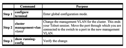
Changing the Management VLAN Through a Telnet Connection
Before you start, review the “Management VLANs” section. Beginning in privileged EXEC mode on the command switch, follow these steps to configure the management VLAN interface through a Telnet connection:
Assigning VLAN Port Membership Modes
You configure a port to belong to a VLAN by assigning a membership mode that determines the kind of traffic the port carries and the number of VLANs it can belong to. Table 8-2 lists the membership modes and characteristics.
Table 8-2 Port Membership Modes
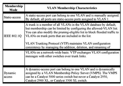
When a port belongs to a VLAN, the switch learns and manages the addresses associated with the port on a per-VLAN basis.
VLAN Membership Combinations
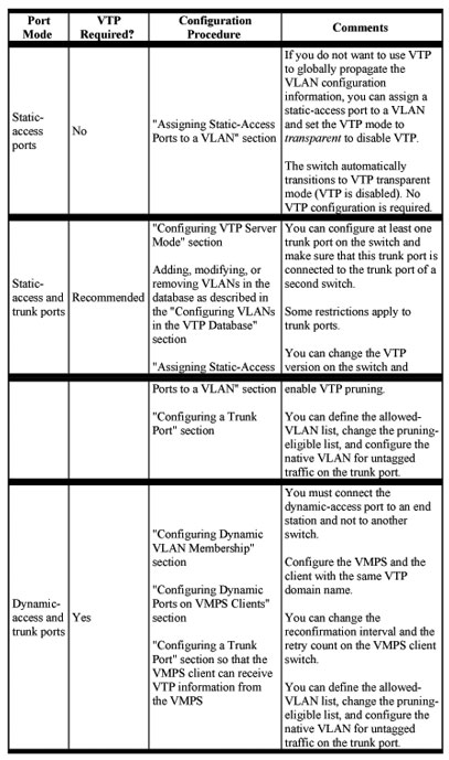
You can configure your switch ports in the various VLAN membership combinations in Table 8-3.
Table 8-3 VLAN Combinations
Assigning Static-Access Ports to a VLAN
By default, all ports are static-access ports assigned to the management VLAN, VLAN 1.
You can assign a static-access port to a VLAN without having VTP globally propagate VLAN configuration information (VTP is disabled). Configuring the switch for VTP transparent mode disables VTP.
Using VTP
VTP is a Layer 2 messaging protocol that maintains VLAN configuration consistency by managing the addition, deletion, and renaming of VLANs on a network-wide basis. VTP minimizes misconfigurations and configuration inconsistencies that can cause several problems, such as duplicate VLAN names, incorrect VLAN-type specifications, and security violations.
Before you create VLANs, you must decide whether to use VTP in your network. Using VTP, you can make configuration changes centrally on a single switch, such as a Catalyst 2950 switch, and have those changes automatically communicated to all the other switches in the network. Without VTP, you cannot send information about VLANs to other switches.
The VTP Domain
A VTP domain (also called a VLAN management domain) consists of one switch or several interconnected switches under the same administrative responsibility. A switch can be in only one VTP domain. You make global VLAN configuration changes for the domain by using the CLI, Cluster Management Suite, or SNMP.
By default, a Catalyst 2950 switch is in the no-management-domain state until it receives an advertisement for a domain over a trunk link (a link that carries the traffic of multiple VLANs) or until you configure a domain name. The default VTP mode is server mode, but VLAN information is not propagated over the network until a domain name is specified or learned.
If the switch receives a VTP advertisement over a trunk link, it inherits the domain name and configuration revision number. The switch then ignores advertisements with a different domain name or an earlier configuration revision number.
When you make a change to the VLAN configuration on a VTP server, the change is propagated to all switches in the VTP domain. VTP advertisements are sent over all IEEE 802.1Q trunk connections.
If you configure a switch for VTP transparent mode, you can create and modify VLANs, but the changes are not transmitted to other switches in the domain, and they affect only the individual switch.
VTP Modes and Mode Transitions
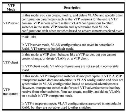
You can configure a supported switch to be in one of the VTP modes listed in Table 8-4. Table 8-4 VTP Modes
These configurations can cause a switch to automatically change its VTP mode:
When the network is configured with more than the maximum 250 VLANs, the switch automatically changes from VTP server or client mode to VTP transparent mode. The switch then operates with the VLAN configuration that preceded the one that sent it into transparent mode.
VTP Advertisements
Each switch in the VTP domain sends periodic global configuration advertisements from each trunk port to a reserved multicast address. Neighboring switches receive these advertisements and update their VTP and VLAN configurations as necessary.
Note Because trunk ports send and receive VTP advertisements, you must ensure that at least one trunk port is configured on the switch and that this trunk port is connected to the trunk port of a second switch. Otherwise, the switch cannot receive any VTP advertisements.
VTP advertisements distribute this global domain information in VTP advertisements:
- VTP domain name
- VTP configuration revision number
- Update identity and update timestamp
- MD5 digest
VTP advertisements distribute this VLAN information for each configured VLAN:
- VLAN ID
- VLAN name
- VLAN type
- VLAN state
- Additional VLAN configuration information specific to the VLAN type
VTP Version 2
VTP version 2 supports these features not supported in version 1:
- Token Ring support—VTP version 2 supports Token Ring LAN switching and VLANs (Token Ring Bridge Relay Function [TrBRF] and Token Ring Concentrator Relay Function [TrCRF]).
- Unrecognized Type-Length-Value (TLV) support—A VTP server or client propagates configuration changes to its other trunks, even for TLVs it is not able to parse. The unrecognized TLV is saved in nonvolatile RAM when the switch is operating in VTP server mode.
- Version-Dependent Transparent Mode—In VTP version 1, a VTP transparent switch inspects VTP messages for the domain name and version and forwards a message only if the version and domain name match. Because VTP version 2 supports only one domain, it forwards VTP messages in transparent mode without inspecting the version and domain name.
- Consistency Checks—In VTP version 2, VLAN consistency checks (such as VLAN names and values) are performed only when you enter new information through the CLI, the Cluster Management Suite, or SNMP. Consistency checks are not performed when new information is obtained from a VTP message or when information is read from nonvolatile RAM. If the digest on a received VTP message is correct, its information is accepted without consistency checks.
VTP Pruning
Pruning increases available bandwidth by restricting flooded traffic to those trunk links that the traffic must use to reach the destination devices. Without VTP pruning, a switch floods broadcast, multicast, and unknown unicast traffic across all trunk links within a VTP domain even though receiving switches might discard them.
VTP pruning blocks unneeded flooded traffic to VLANs on trunk ports that are included in the pruning-eligible list. Only VLANs included in the pruning-eligible list can be pruned. By default, VLANs 2 through 1001 are pruning eligible on Catalyst 2950 trunk ports. If the VLANs are configured as pruning-ineligible, the flooding continues. VTP pruning is also supported with VTP version 1 and version 2.
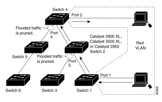
Figure 8-2 shows a switched network with VTP pruning enabled. The broadcast traffic from Switch 1 is not forwarded to Switches 3, 5, and 6 because traffic for the Red VLAN has been pruned on the links shown (port 5 on Switch 2 and port 4 on Switch 4).
Figure 8-2 Optimized Flooded Traffic with VTP Pruning
VTP Configuration Guidelines
These sections describe the guidelines you should follow when configuring the VTP domain name and password and the VTP version number.
Domain Names
When configuring VTP for the first time, you must always assign a domain name. You must also configure all switches in the VTP domain with the same domain name. Switches in VTP transparent mode do not exchange VTP messages with other switches, and you do not need to configure a VTP domain name for them.
Caution Do not configure a VTP domain if all switches are operating in VTP client mode. If you configure the domain, it is impossible to make changes to the VLAN configuration of that domain. Therefore, make sure you configure at least one switch in the VTP domain for VTP server mode.
Passwords
You can configure a password for the VTP domain, but it is not required. All domain switches must share the same password. Switches without a password or with the wrong password reject VTP advertisements.
Caution The domain does not function properly if you do not assign the same password to each switch in the domain.
If you configure a VTP password for a domain, a Catalyst 2950 switch that is booted without a VTP configuration does not accept VTP advertisements until you configure it with the correct password. After the configuration, the switch accepts the next VTP advertisement that uses the same password and domain name in the advertisement.
If you are adding a new switch to an existing network with VTP capability, the new switch learns the domain name only after the applicable password has been configured on the switch.
Upgrading from Previous Software Releases
When you upgrade from a software version that supports VLANs but does not support VTP, such as Cisco IOS Release 12.0(5.1)WC, to a version that does support VTP, ports that belong to a VLAN retain their VLAN membership, and VTP enters transparent mode. The domain name becomes UPGRADE, and VTP does not propagate the VLAN configuration to other switches.
If you want the switch to propagate VLAN configuration information to other switches and to learn the VLANs enabled on the network, you must configure the switch with the correct domain name, the domain password, and change the VTP mode to VTP server.
VTP Version
Follow these guidelines when deciding which VTP version to implement:
- All switches in a VTP domain must run the same VTP version.
- A VTP version 2-capable switch can operate in the same VTP domain as a switch running VTP version 1 if version 2 is disabled on the version 2-capable switch. Version 2 is disabled by default.
- Do not enable VTP version 2 on a switch unless all of the switches in the same VTP domain are version-2-capable. When you enable version 2 on a switch, all of the version-2-capable switches in the domain enable version 2. If there is a version 1-only switch, it will not exchange VTP information with switches with version 2 enabled.
- If there are Token Ring networks in your environment (TRBRF and TRCRF), you must enable VTP version 2 so that Token Ring VLAN switching functions properly. To run Token Ring and Token Ring-Net, disable VTP version 2.
- Enabling or disabling VTP pruning on a VTP server enables or disables VTP pruning for the entire VTP domain.
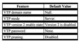
Default VTP Configuration
Table 8-5 shows the default VTP configuration.
Table 8-5 VTP Default Configuration
Configuring VTP
You can configure VTP through the CLI by entering commands in the VLAN database command mode. When you enter the exit command in VLAN database mode, it applies all the commands that you entered. VTP messages are sent to other switches in the VTP domain, and you enter privileged EXEC mode. If you are configuring VTP on a cluster member switch to a VLAN, use the rcommand privileged EXEC command to log in to the member switch. For more information on how to use this command, refer to the Catalyst 2950 Desktop Switch Command Reference.
Note The Cisco IOS end and Ctrl-Z commands are not supported in VLAN database mode.
After you configure VTP, you must configure a trunk port so that the switch can send and receive VTP advertisements.
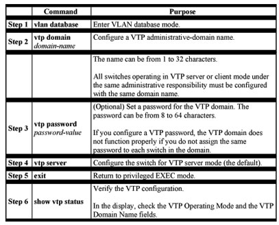
Configuring VTP Server Mode
When a switch is in VTP server mode, you can change the VLAN configuration and have it propagated throughout the network.
Beginning in privileged EXEC mode, follow these steps to configure the switch for VTP server mode:
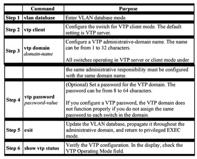
Configuring VTP Client Mode
When a switch is in VTP client mode, you cannot change its VLAN configuration. The client switch receives VTP updates from a VTP server in the VTP domain and then modifies its configuration accordingly.
Caution Do not configure a VTP domain name if all switches are operating in VTP client mode. If you do so, it is impossible to make changes to the VLAN configuration of that domain. Therefore, make sure you configure at least one switch as the VTP server.
Beginning in privileged EXEC mode, follow these steps to configure the switch for VTP client mode:
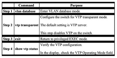
Disabling VTP (VTP Transparent Mode)
When you configure the switch for VTP transparent mode, you disable VTP on the switch. The switch then does not send VTP updates and does not act on VTP updates received from other switches. However, a VTP transparent switch does forward received VTP advertisements on all of its trunk links.
Beginning in privileged EXEC mode, follow these steps to configure the switch for VTP transparent mode:
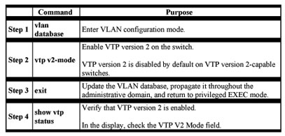
Enabling VTP Version 2
VTP version 2 is disabled by default on VTP version 2-capable switches. When you enable VTP version 2 on a switch, every VTP version 2-capable switch in the VTP domain enables version 2.
Caution VTP version 1 and VTP version 2 are not interoperable on switches in the same VTP domain. Every switch in the VTP domain must use the same VTP version. Do not enable VTP version 2 unless every switch in the VTP domain supports version 2.
Note In a Token Ring environment, you must enable VTP version 2 for Token Ring VLAN switching to function properly.
Beginning in privileged EXEC mode, follow these steps to enable VTP version 2:
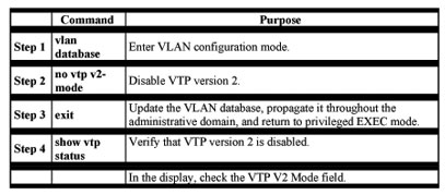
Disabling VTP Version 2
Beginning in privileged EXEC mode, follow these steps to disable VTP version 2:
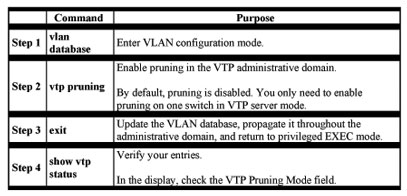
Enabling VTP Pruning
Pruning increases available bandwidth by restricting flooded traffic to those trunk links that the traffic must use to access the destination devices. You enable VTP pruning on a switch in VTP server mode.
Pruning is supported with VTP version 1 and version 2. If you enable pruning on the VTP server, it is enabled for the entire VTP domain.
Only VLANs included in the pruning-eligible list can be pruned. By default, VLANs 2 through 1001 are pruning-eligible on Catalyst 2950 trunk portsBeginning in privileged EXEC mode, follow these steps to enable VTP pruning:
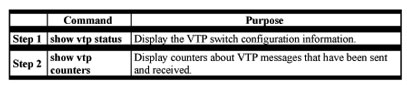
Monitoring VTP
You monitor VTP by displaying its configuration information: the domain name, the current VTP revision, and the number of VLANs. You can also display statistics about the advertisements sent and received by the switch.
Beginning in privileged EXEC mode, follow these steps to monitor VTP activity:
VLANs in the VTP Database
You can set these parameters when you add a new VLAN to or modify an existing VLAN in the VTP database:
- VLAN ID
- VLAN name
- VLAN type (Ethernet, Fiber Distributed Data Interface [FDDI], FDDI network entity title [NET], TRBRF or TRCRF, Token Ring, Token Ring-Net)
- VLAN state (active or suspended)
- Maximum transmission unit (MTU) for the VLAN
- Security Association Identifier (SAID)
- Bridge identification number for TRBRF VLANs
- Ring number for FDDI and TRCRF VLANs
- Parent VLAN number for TRCRF VLANs
- STP type for TRCRF VLANs
- VLAN number to use when translating from one VLAN type to another
Token Ring VLANs
Although the Catalyst 2950 switches do not support Token Ring connections, a remote device such as a Catalyst 5000 series switch with Token Ring connections could be managed from one of the supported switches. Switches running this IOS release advertise information about these Token Ring VLANs when running VTP version 2:
- Token Ring TRBRF VLANs
- Token Ring TRCRF VLANs
For more information on configuring Token Ring VLANs, refer to the Catalyst 5000 Series Software Configuration Guide.
VLAN Configuration Guidelines
Follow these guidelines when creating and modifying VLANs in your network:
- A maximum of 250 VLANs can be active on supported switches. If VTP reports that there are 254 active VLANs, 4 of the active VLANs (1002 to 1005) are reserved for Token Ring and FDDI.
- Before you can create a VLAN, the switch must be in VTP server mode or VTP transparent mode.
- Switches running this IOS release do not support Token Ring or FDDI media. The switch does not forward FDDI, FDDI-Net, TRCRF, or TRBRF traffic, but it does propagate the VLAN configuration through VTP.
Default VLAN Configuration
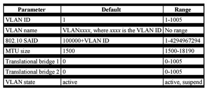
Table 8-6 shows the default configuration for the Ethernet VLAN default and ranges.
Note Catalyst 2950 switches support Ethernet interfaces exclusively. Because FDDI and Token Ring VLANs are not locally supported, you configure FDDI and Token Ring media-specific characteristics only for VTP global advertisements to other switches.
Table 8-6 Ethernet VLAN Defaults and Ranges
Configuring VLANs in the VTP Database
You use the CLI vlan database VLAN database command to add, change, and delete VLANs. In VTP server or transparent mode, commands to add, change, and delete VLANs are written to the vlan.dat file, and you can display them by entering the privileged EXEC show vlan command. The vlan.dat file is stored in nonvolatile RAM. The vlan.dat file is upgraded automatically, but you cannot return to an earlier version of Cisco IOS after you upgrade to this release.
Caution You can cause inconsistency in the VLAN database if you attempt to manually delete the vlan.dat file. If you want to modify the VLAN configuration or VTP, use the VLAN database commands described in the Catalyst 2950 Desktop Switch Command Reference.
You use the interface configuration command mode to define the port membership mode and add and remove ports from VLANs. The results of these commands are written to the running-configuration file, and you can display the file by entering the privileged EXEC show running-config command.
Note VLANs can be configured to support a number of parameters that are not discussed in detail in this section. For complete information on the commands and parameters that control VLAN configuration, refer to the Catalyst 2950 Desktop Switch Command Reference.
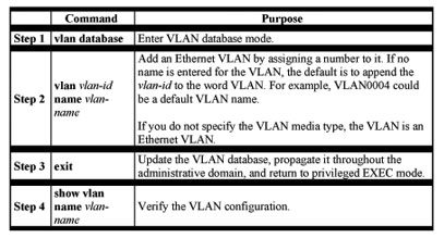
Adding a VLAN
Each VLAN has a unique, 4-digit ID that can be a number from 1 to 1001. To add a VLAN to the VLAN database, assign a number and name to the VLAN..
If you do not specify the VLAN media type, the VLAN is an Ethernet VLAN.
Beginning in privileged EXEC mode, follow these steps to add an Ethernet VLAN:
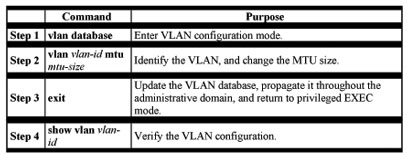
Modifying a VLAN
Beginning in privileged EXEC mode, follow these steps to modify an Ethernet VLAN:
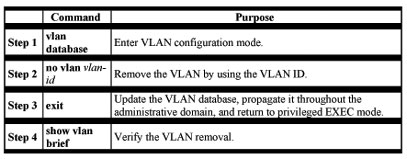
Deleting a VLAN from the Database
When you delete a VLAN from a switch that is in VTP server mode, the VLAN is removed from all switches in the VTP domain. When you delete a VLAN from a switch that is in VTP transparent mode, the VLAN is deleted only on that specific switch.
You cannot delete the default VLANs for the different media types: Ethernet VLAN 1 and FDDI or Token Ring VLANs 1002 to 1005.
Caution When you delete a VLAN, any ports assigned to that VLAN become inactive. They remain associated with the VLAN (and thus inactive) until you assign them to a new VLAN.
Beginning in privileged EXEC mode, follow these steps to delete a VLAN on the switch:
Assigning Static-Access Ports to a VLAN
By default, all ports are in trunk-desirable mode and assigned to VLAN 1, which is the default management VLAN. If you are assigning a port on a cluster member switch to a VLAN, first use the privileged EXEC rcommand command to log in to the member switch. For more information on how to use this command, refer to the Catalyst 2950 Desktop Switch Command Reference.
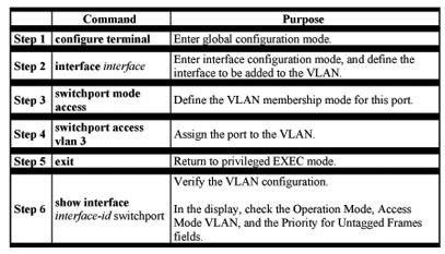
Beginning in privileged EXEC mode, follow these steps to assign a port to a VLAN in the VTP database:
How VLAN Trunks Work
A trunk is a point-to-point link that transmits and receives traffic between switches or between switches and routers. Trunks carry the traffic of multiple VLANs and can extend VLANs across an entire network.
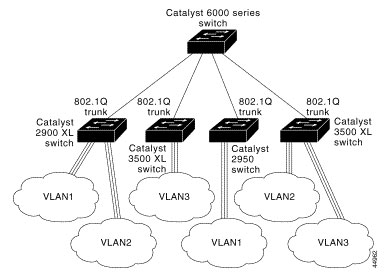
Figure 8-3 shows a network of switches that are connected by 802.1Q trunks.
Figure 8-3 Catalyst 2950, 2900 XL, and 3500 XL Switches in a 802.1Q Trunking Environment
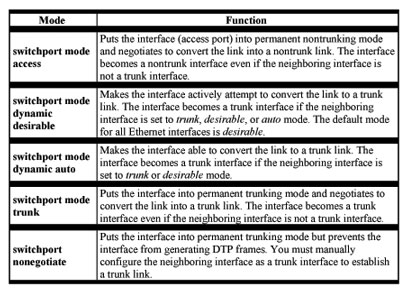
Note DTP is a point-to-point protocol. However, some internetworking devices might forward DTP frames improperly. To avoid this, ensure that interfaces connected to devices that do not support DTP are configured with the access keyword if you do not intend to trunk across those links. To enable trunking to a device that does not support DTP, use the nonegotiate keyword to cause the interface to become a trunk but to not generate DTP frames. See Table 8-7 for more details.
Table 8-7 Interface Modes
IEEE 802.1Q Configuration Considerations
IEEE 802.1Q trunks impose these limitations on the trunking strategy for a network:
- Make sure the native VLAN for a 802.1Q trunk is the same on both ends of the trunk link. If the native VLAN on one end of the trunk is different from the native VLAN on the other end, spanning-tree loops might result.
- Make sure your network is loop-free before disabling STP.
Note The Catalyst 2950 switches do not support ISL trunking.
Trunks Interacting with Other Features
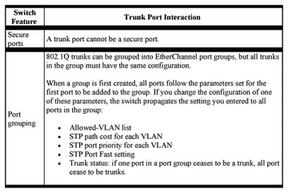
IEEE 802.1Q trunking interacts with other switch features as described in Table 8-8.
Table 8-8 Trunks Interacting with Other Features
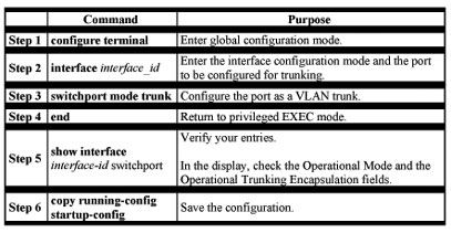
Configuring a Trunk Port
Note Because trunk ports send and receive VTP advertisements, you must ensure that at least one trunk port is configured on the switch and that this trunk port is connected to the trunk port of a second switch. Otherwise, the switch cannot receive any VTP advertisements.
Beginning in privileged EXEC mode, follow these steps to configure a port as a 802.1Q trunk port:
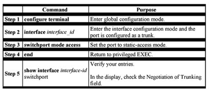
CLI: Disabling a Trunk Port
You can disable trunking on a port by returning it to the dynamic-access mode.
Beginning in privileged EXEC mode, follow these steps to disable trunking on a port:
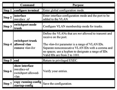
CLI: Defining the Allowed VLANs on a Trunk
By default, a trunk port sends to and receives traffic from all VLANs in the VLAN database. All VLANs, 1 to 1005, are allowed on each trunk. However, you can remove VLANs from the allowed list, preventing traffic from those VLANs from passing over the trunk. To restrict the traffic a trunk carries, use the switchport trunk allowed vlan remove vlan-list interface configuration command to remove specific VLANs from the allowed list.
A trunk port can become a member of a VLAN if the VLAN is enabled, if VTP knows of the VLAN, and if the VLAN is in the allowed list for the port. When VTP detects a newly enabled VLAN and the VLAN is in the allowed list for a trunk port, the trunk port automatically becomes a member of the enabled VLAN. When VTP detects a new VLAN and the VLAN is not in the allowed list for a trunk port, the trunk port does not become a member of the new VLAN.
Beginning in privileged EXEC mode, follow these steps to modify the allowed list of a 802.1Q trunk:
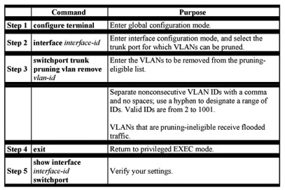
Changing the Pruning-Eligible List
The pruning-eligible list applies only to trunk ports. Each trunk port has its own eligibility list. VTP Pruning must be enabled for this procedure to take effect. The “Enabling VTP Pruning” section describes how to enable VTP pruning.
Beginning in privileged EXEC mode, follow these steps to remove VLANs from the pruning-eligible list on a trunk port:
Configuring the Native VLAN for Untagged Traffic
A trunk port configured with 802.1Q tagging can receive both tagged and untagged traffic. By default, the switch forwards untagged traffic with the native VLAN configured for the port. The native VLAN is VLAN 1 by default.
Note The native VLAN can be assigned any VLAN ID, and it is not dependent on the management VLAN.
Beginning in privileged EXEC mode, follow these steps to configure the native VLAN on an 802.1Q trunk:
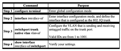
If a packet has a VLAN ID that is the same as the outgoing port native VLAN ID, the packet is transmitted untagged; otherwise, the switch transmits the packet with a tag.
Load Sharing Using STP
Load sharing divides the bandwidth supplied by parallel trunks connecting switches. To avoid loops, STP normally blocks all but one parallel link between switches. With load sharing, you divide the traffic between the links according to which VLAN the traffic belongs.
You configure load sharing on trunk ports by using STP port priorities or STP path costs. For load sharing using STP port priorities, both load-sharing links must be connected to the same switch. For load sharing using STP path costs, each load-sharing link can be connected to the same switch or to two different switches.
Load Sharing Using STP Port Priorities
When two ports on the same switch form a loop, the STP port priority setting determines which port is enabled and which port is in standby mode. You can set the priorities on a parallel trunk port so that the port carries all the traffic for a given VLAN. The trunk port with the higher priority (lower values) for a VLAN is forwarding traffic for that VLAN. The trunk port with the lower priority (higher values) for the same VLAN remains in a blocking state for that VLAN. One trunk port transmits or receives all traffic for the VLAN.
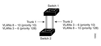
Figure 8-4 shows two trunks connecting supported switches. In this example, the switches are configured as follows:
- VLANs 8 through 10 are assigned a port priority of 10 on trunk 1.
- VLANs 3 through 6 retain the default port priority of 128 on trunk 1.
- VLANs 3 through 6 are assigned a port priority of 10 on trunk 2.
- VLANs 8 through 10 retain the default port priority of 128 on trunk 2.
In this way, trunk 1 carries traffic for VLANs 8 through 10, and trunk 2 carries traffic for VLANs 3 through 6. If the active trunk fails, the trunk with the lower priority takes over and carries the traffic for all of the VLANs. No duplication of traffic occurs over any trunk port.
Figure 8-4 Load Sharing by Using STP Port Priorities
Configuring STP Port Priorities and Load Sharing
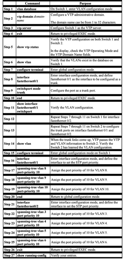
Beginning in privileged EXEC mode, follow these steps to configure the network shown in Figure 8-4:
Load Sharing Using STP Path Cost
You can configure parallel trunks to share VLAN traffic by setting different path costs on a trunk and associating the path costs with different sets of VLANs. The VLANs keep the traffic separate; because no loops exist, STP does not disable the ports; and redundancy is maintained in the event of a lost link.
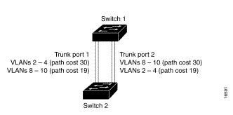
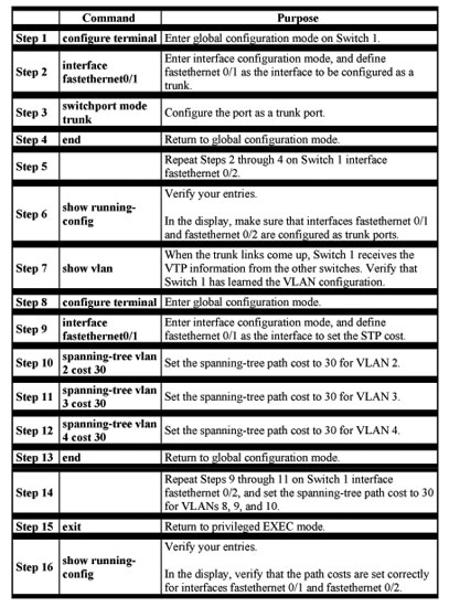
In Figure 8-5, trunk ports 1 and 2 are 100BASE-T ports. The path costs for the VLANs are assigned as follows:
- VLANs 2 through 4 are assigned a path cost of 30 on trunk port 1.
- VLANs 8 through 10 retain the default 100BASE-T path cost on trunk port 1 of 19.
- VLANs 8 through 10 are assigned a path cost of 30 on trunk port 2.
- VLANs 2 through 4 retain the default 100BASE-T path cost on trunk port 2 of 19.
Figure 8-5 Load-Sharing Trunks with Traffic Distributed by Path Cost
Beginning in privileged EXEC mode, follow these steps to configure the network shown in Figure 8-5:
How the VMPS Works
A switch running this software release acts as a client to the VLAN Membership Policy Server (VMPS) and communicates with it through the VLAN Query Protocol (VQP ). When the VMPS receives a VQP request from a client switch, it searches its database for a MAC-address-to-VLAN mapping. The server response is based on this mapping and whether or not the server is in secure mode. Secure mode determines whether the server shuts down the port when a VLAN is not allowed on it or just denies the port access to the VLAN.
In response to a request, the VMPS takes one of these actions:
- If the assigned VLAN is restricted to a group of ports, the VMPS verifies the requesting port against this group and responds as follows:
o If the VLAN is allowed on the port, the VMPS sends the VLAN name to the client in response.
o If the VLAN is not allowed on the port, and the VMPS is not in secure mode, the VMPS sends an access-denied response.
o If the VLAN is not allowed on the port, and the VMPS is in secure mode, the VMPS sends a port-shutdown response. - If the VLAN in the database does not match the current VLAN on the port and active hosts exist on the port, the VMPS sends an access-denied or a portshutdown response, depending on the secure mode of the VMPS.
If the switch receives an access-denied response from the VMPS, it continues to block traffic from the MAC address to or from the port. The switch continues to monitor the packets directed to the port and sends a query to the VMPS when it identifies a new address. If the switch receives a port-shutdown response from the VMPS, it disables the port. The port must be manually reenabled by using the CLI, Cluster Management Suite, or SNMP. You can also use an explicit entry in the configuration table to deny access to specific MAC addresses for security reasons. If you enter the none keyword for the VLAN name, the VMPS sends an access-denied or port-shutdown response.
Dynamic Port VLAN Membership
A dynamic (nontrunking) port on the switch can belong to only one VLAN. When the link comes up, the switch does not forward traffic to or from this port until the VMPS provides the VLAN assignment. The VMPS receives the source MAC address from the first packet of a new host connected to the dynamic port and attempts to match the MAC address to a VLAN in the VMPS database.
If there is a match, the VMPS sends the VLAN number for that port. If the client switch was not previously configured, it uses the domain name from the first VTP packet it receives on its trunk port from the VMPS. If the client switch was previously configured, it includes its domain name in the query packet to the VMPS to obtain its VLAN number. The VMPS verifies that the domain name in the packet matches its own domain name before accepting the request and responds to the client with the assigned VLAN number for the client.
If there is no match, the VMPS either denies the request or shuts down the port (depending on the VMPS secure mode setting).
Multiple hosts (MAC addresses) can be active on a dynamic port if they are all in the same VLAN; however, the VMPS shuts down a dynamic port if more than 20 hosts are active on the port.
If the link goes down on a dynamic port, the port returns to an isolated state and does not belong to a VLAN. Any hosts that come online through the port are checked again with the VMPS before the port is assigned to a VLAN.
VMPS Database Configuration File
The VMPS contains a database configuration file that you create. This ASCII text file is stored on a switch-accessible TFTP server that functions as a VMPS server. The file contains VMPS information, such as the domain name, the fall-back VLAN name, and the MAC address-to-VLAN mapping. A Catalyst 3500, Catalyst 2900, or a Catalyst 2950 switch running this software release cannot act as the VMPS. Use a Catalyst 5000 series switch such as the VMPS.
The VMPS database configuration file on the server must use the Catalyst 2950 convention for naming ports. For example, fastethernet 0/5 is fixed-port number 5.
If the switch is a cluster member, the command switch adds the name of the switch before the Fa. For example, es3%Fa 0/2 refers to fixed 10/100 port 2 on member switch 3. These naming conventions must be used in the VMPS database configuration file when it is configured to support a cluster.
You can configure a fallback VLAN name. If you connect a device with a MAC address that is not in the database, the VMPS sends the fallback VLAN name to the client. If you do not configure a fallback VLAN and the MAC address does not exist in the database, the VMPS sends an access-denied response. If the VMPS is in secure mode, it sends a port-shutdown response.
This example shows a sample VMPS database configuration file as it appears on a Catalyst 5000 series switch.
!vmps domain < domain-name>
! The VMPS domain must be defined.
!vmps mode { open | secure }
! The default mode is open.
!vmps fallback < vlan-name>
!vmps no-domain-req { allow | deny }
!
! The default value is allow.
vmps domain WBU
vmps mode open
vmps fallback default
vmps no-domain-req deny
!
!
!MAC Addresses
!
vmps-mac-addrs
!
! address < addr> vlan-name < vlan_name>
!
address 0012.2233.4455 vlan-name hardware
address 0000.6509.a080 vlan-name hardware
address aabb.ccdd.eeff vlan-name Green
address 1223.5678.9abc vlan-name ExecStaff
address fedc.ba98.7654 vlan-name –NONE–
address fedc.ba23.1245 vlan-name Purple
!
!Port Groups
!
!vmps-port-group < group-name>
! device < device-id> { port < port-name> | all-ports }
!
vmps-port-group WiringCloset1
device 192.168.1.1 port Fa1/3
device 172.16.1.1 port Fa1/4
vmps-port-group “Executive Row”
device 192.168.2.2 port es5%Fa0/1
device 192.168.2.2 port es5%Fa0/2
device 192.168.2.3 all-ports
!
!VLAN groups
!
!vmps-vlan-group < group-name>
! vlan-name < vlan-name>
!
vmps-vlan-group Engineering
vlan-name hardware
vlan-name software
!
!VLAN port Policies
!
!vmps-port-policies {vlan-name < vlan_name> | vlan-group < group-name> }
! { port-group < group-name> | device < device-id> port < port-name> }
!
vmps-port-policies vlan-group Engineering
port-group WiringCloset1
vmps-port-policies vlan-name Green
device 192.168.1.1 port Fa0/9
vmps-port-policies vlan-name Purple
device 192.168.2.2 port Fa0/10
port-group “Executive Row”VMPS Configuration Guidelines
These guidelines and restrictions apply to dynamic port VLAN membership:
- You must configure the VMPS before you configure ports as dynamic.
- The communication between a cluster of switches and VMPS is managed by the command switch and includes port-naming conventions that are different from standard port names.
- When the port is configured as dynamic access port, it changes to an unassigned VLAN state until it is assigned a valid VLAN by VMPS. The Port Fast feature is also automatically enabled when the port is assigned with a valid VLAN by VMPS.
- Secure ports cannot be dynamic ports. You must disable port security on the port before it becomes dynamic.
- Trunk ports cannot be dynamic ports, but it is possible to enter the switchport access vlan dynamic interface configuration command for a trunk port. In this case, the switch retains the setting and applies it if the port is later configured as an access port.
You must turn off trunking on the port before the dynamic access setting takes effect.
- Dynamic ports cannot be network ports or monitor ports.
- The VTP management domain of the VMPS client and the VMPS server must be the same.
- Physical ports in a port channel cannot be configured as dynamic ports.
- Port channels cannot be configured as dynamic ports.
- 802.1X ports cannot be configured as dynamic ports.
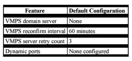
Default VMPS Configuration
Table 8-9 shows the default VMPS and dynamic port configuration on client switches.
Table 8-9 Default VMPS Client and Dynamic Port Configuration
Configuring Dynamic VLAN Membership
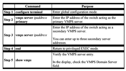
You must enter the IP address of the Catalyst 5000 switch or the other device acting as the VMPS to configure the Catalyst 2950 switch as a client. If the VMPS is being defined for a cluster of switches, enter the address on the command switch.
Beginning in privileged EXEC mode, follow these steps to enter the IP address of the VMPS:
Configuring Dynamic Ports on VMPS Clients
If you are configuring a port on a member switch as a dynamic port, first use the privileged EXEC rcommand command to log into the member. For more information on how to use this command, refer to the Catalyst 2950 Desktop Switch Command Reference.
Caution Dynamic port VLAN membership is for end stations. Connecting dynamic ports to other switches can cause a loss of connectivity.
Beginning in privileged EXEC mode, follow these steps to configure a dynamic port on the VMPS client switches:
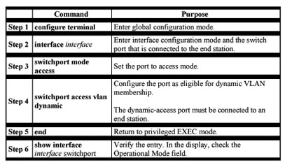
Configure the switch port that is connected to the VMPS server as a trunk.
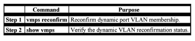
Reconfirming VLAN Memberships
Beginning in privileged EXEC mode, follow these steps to confirm the dynamic port VLAN membership assignments that the switch has received from the VMPS:
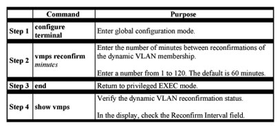
Changing the Reconfirmation Interval
VMPS clients periodically reconfirm the VLAN membership information received from the VMPS. You can set the number of minutes after which reconfirmation occurs. If you are configuring a member switch in a cluster, this parameter must be equal to or greater than the reconfirmation setting on the command switch. You also must first use the privileged EXEC rcommand command to log into the member s. For more information about this command, refer to the Catalyst 2950 Desktop Switch Command Reference.
Beginning in privileged EXEC mode, follow these steps to change the reconfirmation interval:
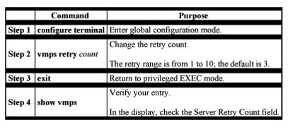
Changing the Retry Count
Beginning in privileged EXEC mode, follow these steps to change the number of times that the switch attempts to contact the VMPS before querying the next server:
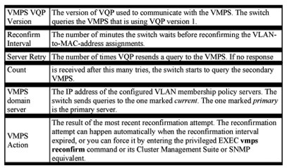
Administering and Monitoring the VMPS
You can display information about the VMPS by using the privileged EXEC show vmps command. The switch displays the this information about the VMPS:
Troubleshooting Dynamic Port VLAN Membership
The VMPS shuts down a dynamic port under these conditions:
- The VMPS is in secure mode, and it will not allow the host to connect to the port. The VMPS shuts down the port to prevent the host from connecting to the network.
- More than 20 active hosts reside on a dynamic port.
To reenable a shut-down dynamic port, enter the interface configuration no shutdown command.
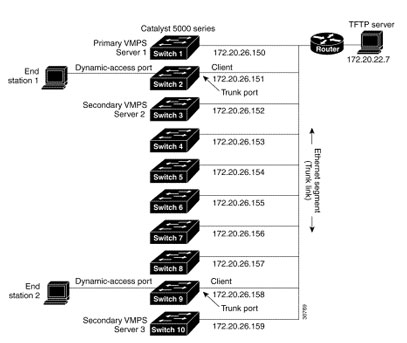
Dynamic Port VLAN Membership Configuration Example
Figure 8-6 shows a network with a VMPS server switch and VMPS client switches with dynamic ports. In this example, these assumptions apply:
- The VMPS server and the VMPS client are separate switches.
- The Catalyst 5000 series Switch 1 is the primary VMPS server.
- The Catalyst 5000 series Switch 3 and Switch 10 are secondary VMPS servers.
- The end stations are connected to these clients:
o Catalyst 2950 Switch 2
o Catalyst 3500 XL Switch 9 - The database configuration file is called Bldg-G.db and is stored on the TFTP server with the IP address 172.20.22.7.
Figure 8-6 Dynamic Port VLAN Membership Configuration
I hope you found this article to be of use and it helps you prepare for your Cisco CCNA certification. Achieving your CCNA certification is much more than just memorizing Cisco exam material. It is having the real world knowledge to configure your Cisco equipment and be able to methodically troubleshoot Cisco issues. So I encourage you to continue in your studies for your CCNA exam certification.