In preparation of our CCNA exam, we want to make sure we cover the various concepts that we could see on our Cisco CCNA exam. So to assist you, below we will discuss the EIGRP routing protocol.
Introduction
Enhanced Interior Gateway Routing Protocol (EIGRP) is an interior gateway protocol suited for many different topologies and media. In a well designed network, EIGRP scales well and provides extremely quick convergence times with minimal network traffic.
EIGRP Theory of Operation
Some of the many advantages of EIGRP are:
- very low usage of network resources during normal operation; only hello packets are transmitted on a stable network
- when a change occurs, only routing table changes are propagated, not the entire routing table; this reduces the load the routing protocol itself places on the network
- rapid convergence times for changes in the network topology (in some situations convergence can be almost instantaneous)
EIGRP is an enhanced distance vector protocol, relying on the Diffused Update Algorithm (DUAL) to calculate the shortest path to a destination within a network.
Major Revisions of the Protocol
There are two major revisions of EIGRP, versions 0 and 1. Cisco IOS versions earlier than 10.3(11), 11.0(8), and 11.1(3) run the earlier version of EIGRP; some explanations in this paper may not apply to that earlier version. We highly recommend using the later version of EIGRP, as it includes many performance and stability enhancements.
Basic Theory
A typical distance vector protocol saves the following information when computing the best path to a destination: the distance (total metric or distance, such as hop count) and the vector (the next hop). For instance, all the routers in the network in Figure 1 are running Routing Information Protocol (RIP). Router Two chooses the path to Network A by examining the hop count through each available path.
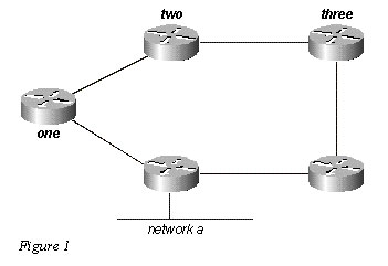
Since the path through Router Three is three hops, and the path through Router One is two hops, Router Two chooses the path through One and discards the information it learned through Three. If the path between Router One and Network A goes down, Router Two loses all connectivity with this destination until it times out the route of its routing table (three update periods, or 90 seconds), and Router Three re-advertises the route (which occurs every 30 seconds in RIP). Not including any hold-down time, it will take between 90 and 120 seconds for Router Two to switch the path from Router One to Router Three. EIGRP, instead of counting on full periodic updates to re-converge, builds a topology table from each of its neighbor’s advertisements (rather than discarding the data), and converges by either looking for a likely loop-free route in the topology table, or, if it knows of no other route, by querying its neighbors. Router Two saves the information it received from both Routers One and Three. It chooses the path through One as its best path (the successor) and the path through Three as a loop-free path (a feasible successor). When the path through Router One becomes unavailable, Router Two examines its topology table and, finding a feasible successor, begins using the path through Three immediately. From this brief explanation, it is apparent that EIGRP must provide:
- a system where it sends only the updates needed at a given time; this is accomplished through neighbor discovery and maintenance
- a way of determining which paths a router has learned are loop-free
- a process to clear bad routes from the topology tables of all routers on the network
- a process for querying neighbors to find paths to lost destinations
We will cover each of these requirements in turn.
Neighbor Discovery and Maintenance
To distribute routing information throughout a network, EIGRP uses non-periodic incremental routing updates. That is, EIGRP only sends routing updates about paths that have changed when those paths change.
The basic problem with sending only routing updates is that you may not know when a path through a neighboring router is no longer available. You can not time out routes, expecting to receive a new routing table from your neighbors. EIGRP relies on neighbor relationships to reliably propagate routing table changes throughout the network; two routers become neighbors when they see each other’s hello packets on a common network.
EIGRP sends hello packets every 5 seconds on high bandwidth links and every 60 seconds on low bandwidth multipoint links.
- 5-second hello:broadcast media, such as Ethernet, Token Ring, and FDDI
point-to-point serial links, such as PPP or HDLC leased circuits, Frame Relay point-to-point subinterfaces, and ATM point-to-point subinterface
high bandwidth (greater than T1) multipoint circuits, such as ISDN PRI and Frame Relay - 60-second hello:multipoint circuits T1 bandwidth or slower, such as Frame Relay multipoint interfaces, ATM multipoint interfaces, ATM switched virtual circuits, and ISDN BRIs
The rate at which EIGRP sends hello packets is called the hello interval, and you can adjust it per interface with the ip hello-interval eigrp command. The hold time is the amount of time that a router will consider a neighbor alive without receiving a hello packet. The hold time is typically three times the hello interval, by default, 15 seconds and 180 seconds. You can adjust the hold time with the ip hold-time eigrp command.
Note that if you change the hello interval, the hold time is not automatically adjusted to account for this change – you must manually adjust the hold time to reflect the configured hello interval.
It is possible for two routers to become EIGRP neighbors even though the hello and hold timers do not match. The hold time is included in the hello packets so each neighbor should stay alive even though the hello interval and hold timers do not match.
While there is no direct way of determining what the hello interval is on a router, you can infer it from the output of show ip eigrp neighbor on the neighboring router.
If you have the output of a show ip eigrp neighbor command from your Cisco device, you can use Output Interpreter ( registered customers only) to display potential issues and fixes. To use Output Interpreter, you must have JavaScript enabled.
router# show ip eigrp neighbor
IP-EIGRP neighbors for process 1
H Address Interface Hold Uptime SRTT RTO Q Seq Type
(sec) (ms) Cnt Num
1 10.1.1.2 Et1 13 12:00:53 12 300 0 620
0 10.1.2.2 S0 174 12:00:56 17 200 0 645
rp-2514aa# show ip eigrp neighbor
IP-EIGRP neighbors for process 1
H Address Interface Hold Uptime SRTT RTO Q Seq Type
(sec) (ms) Cnt Num
1 10.1.1.2 Et1 12 12:00:55 12 300 0 620
0 10.1.2.2 S0 173 12:00:57 17 200 0 645
rp-2514aa# show ip eigrp neighbor
IP-EIGRP neighbors for process 1
H Address Interface Hold Uptime SRTT RTO Q Seq Type
(sec) (ms) Cnt Num
1 10.1.1.2 Et1 11 12:00:56 12 300 0 620
0 10.1.2.2 S0 172 12:00:58 17 200 0 645
The value in the Hold column of the command output should never exceed the hold time, and should never be less than the hold time minus the hello interval (unless, of course, you are losing hello packets). If the Hold column usually ranges between 10 and 15 seconds, the hello interval is 5 seconds and the hold time is 15 seconds. If the Hold column usually has a wider range – between 120 and 180 seconds – the hello interval is 60 seconds and the hold time is 180 seconds. If the numbers do not seem to fit one of the default timer settings, check the interface in question on the neighboring router – the hello and hold timers may have been configured manually.
Note:
- EIGRP does not build peer relationships over secondary addresses. All EIGRP traffic is sourced from the primary address of the interface.
- When configuring EIGRP over a multi-access Frame Relay network (point-to-multipoint, and so on), configure the broadcast keyword in the frame-relay map statements. Without the broadcast keyword the adjacencies would not establish between two EIGRP routers. Refer to Configuring and Troubleshooting Frame Relay for more information.
- There are no limitations on the number of neighbors that EIGRP can support. The actual number of supported neighbors depends on the capability of the device, such as:
- memory capacity
- processing power
- amount of exchanged information, such as the number of routes sent
- topology complexity
- network stability
Building the Topology Table
Now that these routers are talking to each other, what are they talking about? Their topology tables, of course! EIGRP, unlike RIP and IGRP, does not rely on the routing (or forwarding) table in the router to hold all of the information it needs to operate. Instead, it builds a second table, the topology table, from which it installs routes in the routing table.
Note: As of Cisco IOS versions 12.0T and 12.1, RIP maintains its own database from which it installs routes into the routing table.
To see the basic format of the topology table on a router running EIGRP, issue the show ip eigrp topology command. The topology table contains the information needed to build a set of distances and vectors to each reachable network, including:
- lowest bandwidth on the path to this destination as reported by the upstream neighbor
- total delay
- path reliability
- path loading
- minimum path maximum transmission unit (MTU)
- feasible distance
- reported distance
- route source (external routes are marked)
Feasible and reported distance are discussed later in this section.
If you have the output of a show ip eigrp topology command from your Cisco device, you can use Output Interpreter ( registered customers only) to display potential issues and fixes. To use Output Interpreter, you must have JavaScript enabled.
EIGRP Metrics
EIGRP uses the minimum bandwidth on the path to a destination network and the total delay to compute routing metrics. Although you can configure other metrics, we do not recommend it, as it can cause routing loops in your network. The bandwidth and delay metrics are determined from values configured on the interfaces of routers in the path to the destination network.
For instance, in Figure 2 below, Router One is computing the best path to Network A.
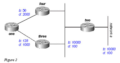
It starts with the two advertisements for this network: one through Router Four, with a minimum bandwidth of 56 and a total delay of 2200; and the other through Router Three, with a minimum bandwidth of 128 and a delay of 1200. Router One chooses the path with the lowest metric.
Let us compute the metrics. EIGRP calculates the total metric by scaling the bandwidth and delay metrics. EIGRP uses the following formula to scale the bandwidth:
- bandwidth = (10000000/bandwidth(i)) * 256where bandwidth(i) is the least bandwidth of all outgoing interfaces on the route to the destination network represented in kilobits.
EIGRP uses the following formula to scale the delay:
- delay = delay(i) * 256where delay(i) is the sum of the delays configured on the interfaces, on the route to the destination network, in tens of microseconds. The delay as shown in the show ip eigrp topology or show interface commands is in microseconds, so you must divide by 10 before you use it in this formula. Throughout this paper, we use delay as it is configured and shown on the interface.
EIGRP uses these scaled values to determine the total metric to the network:
- metric = [K1 * bandwidth + (K2 * bandwidth) / (256 – load) + K3 * delay] * [K5 / (reliability + K4)]
Note: These K values should be used after careful planning. Mismatched K values prevent a neighbor relationship from being built, which can cause your network to fail to converge.
Note: If K5 = 0, the formula reduces to Metric = [k1 * bandwidth + (k2 * bandwidth)/(256 – load) + k3 * delay].
The default values for K are:
- K1 = 1
- K2 = 0
- K3 = 1
- K4 = 0
- K5 = 0
For default behavior, you can simplify the formula as follows:
metric = bandwidth + delay
Cisco routers do not perform floating point math, so at each stage in the calculation, you need to round down to the nearest integer to properly calculate the metrics. In this example, the total cost through Router Four is:
In this example, the total cost through Router Four is:
minimum bandwidth = 56k
total delay = 100 + 100 + 2000 = 2200
[(10000000/56) + 2200] x 256 = (178571 + 2200) x 256 = 180771 x 256 = 46277376And the total cost through Router Three is:
minimum bandwidth = 128k
total delay = 100 + 100 + 1000 = 1200
[(10000000/128) + 1200] x 256 = (78125 + 1200) x 256 = 79325 x 256 = 20307200So to reach Network A, Router One chooses the route through Router Three.
Note the bandwidth and delay values we used are those configured on the interface through which the router reaches its next hop to the destination network. For example, Router Two advertised Network A with the delay configured on its Ethernet interface; Router Four added the delay configured on its Ethernet, and Router One added the delay configured on its serial.
Feasible Distance, Reported Distance, and Feasible Successor
Feasible distance is the best metric along a path to a destination network, including the metric to the neighbor advertising that path. Reported distance is the total metric along a path to a destination network as advertised by an upstream neighbor. A feasible successor is a path whose reported distance is less than the feasible distance (current best path). Figure 3 illustrates this process:
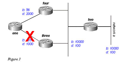
Router One sees that it has two routes to Network A: one through Router Three and another through Router Four.
- The route through Router Four has a cost of 46277376 and a reported distance of 307200.
- The route through Router Three has a cost of 20307200 and a reported distance of 307200.
Note that in each case EIGRP calculates the reported distance from the router advertising the route to the network. In other words, the reported distance from Router Four is the metric to get to Network A from Router Four, and the reported distance from Router Three is the metric to get to Network A from Router Three. EIGRP chooses the route through Router Three as the best path, and uses the metric through Router Three as the feasible distance. Since the reported distance to this network through Router Four is less than the feasible distance, Router One considers the path through Router Four a feasible successor.
When the link between Routers One and Three goes down, Router One examines each path it knows to Network A and finds that it has a feasible successor through Router Four. Router One uses this route, using the metric through Router Four as the new feasible distance. The network converges instantly, and updates to downstream neighbors are the only traffic from the routing protocol.
Let us look at a more complex scenario, shown in Figure 4.
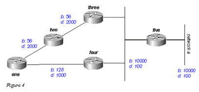
There are two routes to Network A from Router One: one through Router Two with a metric of 46789376 and another through Router Four with a metric of 20307200. Router One chooses the lower of these two metrics as its route to Network A, and this metric becomes the feasible distance. Next, let us look at the path through Router Two to see if it qualifies as a feasible successor. The reported distance from Router Two is 46277376, which is higher than the feasible distance – so this path is not a feasible successor. If you were to look in the topology table of Router One at this point (using show ip eigrp topology), you would only see one entry for Network A – through Router Four. (In reality there are two entries in the topology table at Router One, but only one will be a feasible successor, so the other will not be displayed in show ip eigrp topology; you can see the routes that are not feasible successors using show ip eigrp topology all-links).
Let us suppose that the link between Router One and Router Four goes down. Router One sees that it has lost its only route to Network A, and queries each of its neighbors (in this case, only Router Two) to see if they have a route to Network A. Since Router Two does have a route to Network A, it responds to the query. Since Router One no longer has the better route through Router Four, it accepts this route through Router Two to Network A.
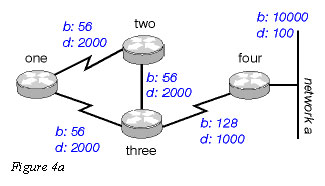
Deciding if a Path is Loop-Free
How does EIGRP use the concepts of feasible distance, reported distance, and feasible successor to determine if a path is valid, and not a loop? In Figure 4a, Router Three examines routes to Network A. Since split horizon is disabled (for example, if these are multipoint Frame Relay interfaces), Router Three shows three routes to Network A: through Router Four, through Router Two (path is two, one, three, four), and through Router One (path is one, two, three, four).
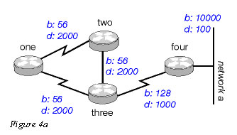
If Router Three accepts all of these routes, it results in a routing loop. Router Three thinks it can get to Network A through Router Two, but the path through Router Two passes through Router Three to get to Network A. If the connection between Router Four and Router Three goes down, Router Three believes it can get to Network A through one of the other paths, but because of the rules for determining feasible successors, it will never use these paths as alternates. Let us look at the metrics to see why:
- total metric to Network A through Router Four: 20281600
- total metric to Network A through Router Two: 47019776
- total metric to Network A through Router One: 47019776
Since the path through Router Four has the best metric, Router Three installs this route in the forwarding table and uses 20281600 as its feasible distance to Network A. Router Three then computes the reported distance to Network A through Routers Two and One: 47019776 for the path through Router Two, and 47019776 for the path through Router One. Because both of these metrics are greater than the feasible distance, Router Three does not install either route as a feasible successor for Network A.
Suppose that the link between Routers Three and Four goes down. Router Three queries each of its neighbors for an alternative route to Network A. Router Two receives the query and, because the query is from its successor, searches each of the other entries in its topology table to see if there is a feasible successor. The only other entry in the topology table is from Router One, with a reported distance equal to the last known best metric through Router Three. Because the reported distance through Router One is not less than the last known feasible distance, Router Two marks the route as unreachable and queries each of its neighbors – in this case, only Router One – for a path to Network A.
Router Three also sends a query for Network A to Router One. Router One examines its topology table and finds that the only other path to Network A is through Router Two with a reported distance equal to the last known feasible distance through Router Three. Once again, since the reported distance through Router Two is not less than the last known feasible distance, this route is not a feasible successor. Router One marks the route as unreachable and queries its only other neighbor, Router Two, for a path to Network A.
This is the first level of queries. Router Three has queried each of its neighbors in an attempt to find a route to Network A. In turn, Routers One and Two have marked the route unreachable, and queried each of their remaining neighbors in an attempt to find a path to Network A. When Router Two receives the Router One query, it examines its topology table and notes that the destination is marked as unreachable. Router Two replies to Router One that Network A is unreachable. When Router One receives the Router Two query, it also sends back a reply that Network A is unreachable. Now Routers One and Two have both concluded that Network A is unreachable, and they reply to the original Router Three query. The network has converged, and all routes return to the passive state.
Split Horizon and Poison Reverse
In the previous example, we assumed that split horizon was not in effect to show how EIGRP uses the feasible distance and the reported distance to determine if a route is likely to be a loop. In some circumstances, however, EIGRP uses split horizon to prevent routing loops as well. Before dealing with the details of how EIGRP uses split horizon, let us review what split horizon is and how it works. The split horizon rule states:
- Never advertise a route out of the interface through which you learned it.
For instance, in Figure 4a, if Router One is connected to Routers Two and Three through a single multipoint interface (such as Frame Relay), and Router One learned about Network A from Router Two, it will not advertise the route to Network A back out the same interface to Router Three. Router One assumes that Router Three would learn about Network A directly from Router Two.
Poison reverse is another way of avoiding routing loops. Its rule states:
- Once you learn of a route through an interface, advertise it as unreachable back through that same interface.
Let us say the routers in Figure 4a have poison reverse enabled. When Router One learns about Network A from Router Two, it advertises Network A as unreachable through its link to Routers Two and Three. Router Three, if it shows any path to Network A through Router One, removes that path because of the unreachable advertisement. EIGRP combines these two rules to help prevent routing loops.
EIGRP uses split horizon or advertises a route as unreachable when:
- two routers are in startup mode (exchanging topology tables for the first time)
- advertising a topology table change
- sending a query
Let us examine each of these situations.
Startup Mode
When two routers first become neighbors, they exchange topology tables during startup mode. For each table entry a router receives during startup mode, it advertises the same entry back to its new neighbor with a maximum metric (poison route).
Topology Table Change
In Figure 5, Router One uses variance to balance the traffic destined to Network A between the two serial links – the 56k link between Routers Two and Four, and the 128k link between Routers Three and Four (see the Load Balancing section for a discussion of variance).
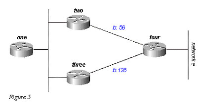
Router Two sees the path through Router Three as a feasible successor. If the link between Routers Two and Four goes down, Router Two simply re-converges on the path through Router Three. Since the split horizon rule states that you should never advertise a route out the interface through which you learned about it, Router Two would not normally send an update. However, this leaves Router One with an invalid topology table entry. When a router changes its topology table in such a way that the interface through which the router reaches a network changes, it turns off split horizon and poison reverses the old route out all interfaces. In this case, Router Two turns off split horizon for this route, and advertises Network A as unreachable. Router One hears this advertisement and flushes its route to Network A through Router Two from its routing table.
Queries
Queries result in a split horizon only when a router receives a query or update from the successor it is using for the destination in the query. Let us take a look at the network in Figure 6.
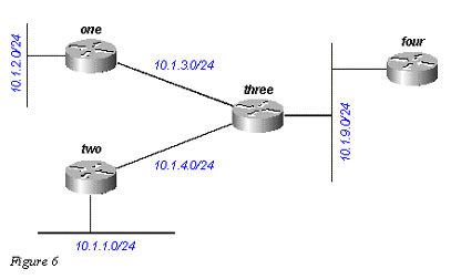
Router Three receives a query concerning 10.1.2.0/24 (which it reaches through Router One) from Router Four. If Three does not have a successor for this destination because a link flap or other temporary network condition, it sends a query to each of its neighbors; in this case, Routers One, Two, and Four. If, however, Router Three receives a query or update (such as a metric change) from Router One for the destination 10.1.2.0/24, it does not send a query back to Router One, because Router One is its successor to this network. Instead, it only sends queries to Routers Two and Four.
Stuck In Active Routes
In some circumstances, it takes a very long time for a query to be answered. So long, in fact, that the router that issued the query gives up and clears its connection to the router that is not answering, effectively restarting the neighbor session. This is known as a stuck in active (SIA) route. The most basic SIA routes occur when it simply takes too long for a query to reach the other end of the network and for a reply to travel back. For instance, in Figure 7, Router One is recording a large number of SIA routes from Router Two.
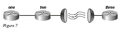
After some investigation, the problem is narrowed down to the delay over the satellite link between Routers Two and Three. There are two possible solutions to this type of problem. The first is to increase the amount of time the router waits after sending a query before declaring the route SIA. This setting can be changed using the timers active-time command.
The better solution, however, is to redesign the network to reduce the range of queries (so very few queries pass over the satellite link). Query range is covered in the Query Range section. Query range in itself, however, is not a common reason for reported SIA routes. More often, some router on the network can not answer a query for one of the following reasons:
- the router is too busy to answer the query (generally due to high CPU utilization)
- the router is having memory problems, and cannot allocate the memory to process the query or build the reply packet
- the circuit between the two routers is not good – enough packets are getting through to keep the neighbor relationship up, but some queries or replies are getting lost between the routers
- unidirectional links (a link on which traffic can only flow in one direction because of a failure)
Troubleshooting SIA Routes
Troubleshooting SIA routes is generally a three-step process:
- Find the routes that are consistently being reported as SIA.
- Find the router that is consistently failing to answer queries for these routes.
- Find the reason that router is not receiving or answering queries.
The first step should be fairly easy. If you are logging console messages, a quick perusal of the log indicates which routes are most frequently marked SIA. The second step is more difficult. The command to gather this information is show ip eigrp topology active:
Codes: P – Passive, A – Active, U – Update, Q – Query, R – Reply,
r – Reply statusA 10.2.4.0/24, 0 successors, FD is 512640000, Q
1 replies, active 00:00:01, query-origin: Local origin
via 10.1.2.2 (Infinity/Infinity), Serial1
1 replies, active 00:00:01, query-origin: Local origin
via 10.1.3.2 (Infinity/Infinity), r, Serial3
Remaining replies:
via 10.1.1.2, r, Serial0Any neighbors that show an R have yet to reply (the active timer shows how long the route has been active). Note that these neighbors may not show up in the Remaining replies section; they may appear among the other RDBs. Pay particular attention to routes that have outstanding replies and have been active for some time, generally two to three minutes. Run this command several times and you begin to see which neighbors are not responding to queries (or which interfaces seem to have a lot of unanswered queries). Examine this neighbor to see if it is consistently waiting for replies from any of its neighbors. Repeat this process until you find the router that is consistently not answering queries. You can look for problems on the link to this neighbor, memory or CPU utilization, or other problems with this neighbor.
If you run into a situation where it seems that the query range is the problem, it is always best to reduce the query range rather than increasing the SIA timer.
Redistribution
This section examines different scenarios involving redistribution. Please note that the examples below show the minimum required to configure redistribution. Redistribution can potentially cause problems, such as below-optimal routing, routing loops, or slow convergence. To avoid these problems, please see “Avoiding Problems Due to Redistribution” in Redistributing Routing Protocols.
Redistribution Between Two EIGRP Autonomous Systems
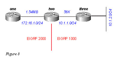
In Figure 8, the routers are configured as follows:
Router One
router eigrp 2000
!— The “2000” is the autonomous system
network 172.16.1.0 0.0.0.255
Router Two
router eigrp 2000
redistribute eigrp 1000 route-map to-eigrp2000
network 172.16.1.0 0.0.0.255
!
router eigrp 1000
redistribute eigrp 2000 route-map to-eigrp1000
network 10.1.0.0 0.0.255.255
route-map to-eigrp1000 deny 10
match tag 1000
!
route-map to-eigrp1000 permit 20
set tag 2000
!
route-map to-eigrp2000 deny 10
match tag 2000
!
route-map to-eigrp2000 permit 20
set tag 1000Router Three
router eigrp 1000
network 10.1.0.0 0.0.255.255Router Three is advertising the network 10.1.2.0/24 to Router Two through autonomous system 1000; Router
Two is redistributing this route into autonomous system 2000 and advertising it to Router One.Note: The routes from EIGRP 1000 are tagged 1000 before redistributing them to EIGRP 2000. When routes from EIGRP 2000 are redistributed back to EIGRP 1000, the routes with 1000 tags are denied to ensure a loop-free topology. For more information on redistribution among routing protocols, please see Redistributing Routing Protocols.
On Router One, we see:
one# show ip eigrp topology 10.1.2.0 255.255.255.0
IP-EIGRP topology entry for 10.1.2.0/24
State is Passive, Query origin flag is 1, 1 Successor(s), FD is 46763776
Routing Descriptor Blocks:
20.1.1.1 (Serial0), from 20.1.1.1, Send flag is 0x0
Composite metric is (46763776/46251776), Route is External
Vector metric:
Minimum bandwidth is 56 Kbit
Total delay is 41000 microseconds
Reliability is 255/255
Load is 1/255
Minimum MTU is 1500
Hop count is 2
External data:
Originating router is 10.1.2.1
AS number of route is 1000
External protocol is EIGRP, external metric is 46251776
Administrator tag is 1000 (0x000003E8)Notice that although the link between Routers One and Two has a bandwidth of 1.544Mb, the minimum bandwidth shown in this topology table entry is 56k. This means that EIGRP preserves all metrics when redistributing between two EIGRP autonomous systems.
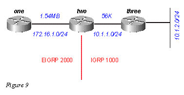
Redistribution Between EIGRP and IGRP in Two Different Autonomous Systems
In Figure 9, we have changed the configurations as follows:
Router One
router eigrp 2000
network 172.16.1.0Router Two
router eigrp 2000
redistribute igrp 1000 route-map to-eigrp2000
network 172.16.1.0
!
router igrp 1000
redistribute eigrp 2000 route-map to-igrp1000
network 10.0.0.0
!
route-map to-igrp1000 deny 10
match tag 1000
!
route-map to-igrp1000 permit 20
set tag 2000
!
route-map to-eigrp2000 deny 10
match tag 2000
!
route-map to-eigrp2000 permit 20
set tag 1000Router Three
router igrp 1000
network 10.0.0.0The configuration for Router One is shown below:
one# show ip eigrp topology 10.1.2.0 255.255.255.0
IP-EIGRP topology entry for 10.1.2.0/24
State is Passive, Query origin flag is 1, 1 Successor(s), FD is 46763776
Routing Descriptor Blocks:
20.1.1.1 (Serial0), from 20.1.1.1, Send flag is 0x0
Composite metric is (46763776/46251776), Route is External
Vector metric:
Minimum bandwidth is 56 Kbit
Total delay is 41000 microseconds
Reliability is 255/255
Load is 1/255
Minimum MTU is 1500
Hop count is 1
External data:
Originating router is 10.1.1.1
AS number of route is 1000
External protocol is IGRP, external metric is 180671
Administrator tag is 1000 (0x000003E8)IGRP metrics are preserved when routes are redistributed into EIGRP with a different autonomous system, but they are scaled by multiplying the IGRP metric by the constant 256. There is one caveat to redistribution between IGRP and EIGRP that should be noted. If the network is directly connected to the router doing the redistribution, it advertises the route with a metric of 1.
For example, the network 10.1.1.0/24 is directly connected to Router Two, and IGRP is routing for this network (there is a network statement under router IGRP that covers this interface). EIGRP is not routing for this network, but is learning about this directly-connected interface through redistribution from IGRP. On Router One, the topology table entry for 10.1.1.0/24 shows:
one# show ip eigrp topology 10.1.1.0 255.255.255.0
IP-EIGRP topology entry for 10.1.1.0/24
State is Passive, Query origin flag is 1, 1 Successor(s), FD is 2169856
Routing Descriptor Blocks:
20.1.1.1 (Serial0), from 20.1.1.1, Send flag is 0x0
Composite metric is (2169856/1), Route is ExternalVector metric:
Minimum bandwidth is 1544 Kbit
Total delay is 20000 microseconds
Reliability is 0/255
Load is 1/255
Minimum MTU is 1500
Hop count is 1
External data:
Originating router is 10.1.1.1
AS number of route is 1000
External protocol is IGRP, external metric is 0
Administrator tag is 1000 (0x000003E8)Note that the reported distance from Router Two, which is bolded, is 1.”
Redistribution Between EIGRP and IGRP in the Same Autonomous System
The following changes are made to the router configurations in Figure 10:

Router One
router eigrp 2000
network 172.16.1.0Router Two
router eigrp 2000
network 172.16.1.0
!
router igrp 2000
network 10.0.0.0Router Three
router igrp 2000
network 10.0.0.0And Router One is configured as follows:
one# show ip eigrp topology 10.1.2.0 255.255.255.0
IP-EIGRP topology entry for 10.1.2.0/24
State is Passive, Query origin flag is 1, 1 Successor(s), FD is 46763776
Routing Descriptor Blocks:
20.1.1.1 (Serial0), from 20.1.1.1, Send flag is 0x0
Composite metric is (46763776/46251776), Route is External
Vector metric:
Minimum bandwidth is 56 Kbit
Total delay is 41000 microseconds
Reliability is 255/255
Load is 1/255
Minimum MTU is 1500
Hop count is 1
External data:
Originating router is 10.1.1.1
AS number of route is 2000
External protocol is IGRP, external metric is 180671
Administrator tag is 0 (0x00000000)So this network, which is directly connected to Router One, is redistributed from IGRP to EIGRP with a metric of 1 – the same metric we see when redistributing between two different autonomous systems. There are two caveats with EIGRP/IGRP redistribution within the same autonomous system:
- Internal EIGRP routes are always preferred over external EIGRP or IGRP routes.
- External EIGRP route metrics are compared to scaled IGRP metrics (the administrative distance is ignored).
Let us examine these caveats in Figure 11:
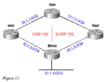
Router One advertises 10.1.4.0/24 in IGRP autonomous system 100; Router Four advertises 10.1.4.0/24 as an external in EIGRP autonomous system 100; Router Two runs both EIGRP and IGRP in autonomous system 100.
If we ignore the EIGRP route advertised by Router Four (by shutting down the link between Routers Two and Four, for instance), Router Two shows:
two# show ip route 10.1.4.0
Routing entry for 10.1.4.0/24
Known via “igrp 100”, distance 100, metric 12001
Redistributing via igrp 100, eigrp 100
Advertised by igrp 100 (self originated)
eigrp 100
Last update from 10.1.1.2 on Serial1, 00:00:42 ago
Routing Descriptor Blocks:
* 10.1.1.2, from 10.1.1.2, 00:00:42 ago, via Serial1
Route metric is 12001, traffic share count is 1
Total delay is 20010 microseconds, minimum bandwidth is 1000 Kbit
Reliability 1/255, minimum MTU 1 bytes
Loading 1/255, Hops 0Note the administrative distance is 100. When we add the EIGRP route, Router Two shows:
two# show ip route 10.1.4.0
Routing entry for 10.1.4.0/24
Known via “eigrp 100”, distance 170, metric 3072256, type external
Redistributing via igrp 100, eigrp 100
Last update from 10.1.2.2 on Serial0, 00:53:59 ago
Routing Descriptor Blocks:
* 10.1.2.2, from 10.1.2.2, 00:53:59 ago, via Serial0
Route metric is 3072256, traffic share count is 1
Total delay is 20010 microseconds, minimum bandwidth is 1000 Kbit
Reliability 1/255, minimum MTU 1 bytes
Loading 1/255, Hops 1
Note the metrics for these two routes are the same after being scaled from IGRP to EIGRP (see the Metrics section):- 12001 x 256 = 3072256
where 12001, an IGRP metric, is through Router One; and 3072256, an EIGRP metric, is through Router Four.
Router Two prefers the EIGRP external route with the same metric (after scaling) and a higher administrative distance. This is true whenever automatic redistribution occurs between EIGRP and IGRP within the same autonomous system. The router always prefers the path with the lowest cost metric and ignores the administrative distance.
Redistribution To and From Other Protocols
Redistribution between EIGRP and other protocols – RIP and OSPF, for example – works in the same way as all redistribution. It is always best to use the default metric when redistributing between protocols. You should be aware of the following two issues when redistributing between EIGRP and other protocols:
- Routes redistributed into EIGRP are not always summarized – see the Summarization section for an explanation.
- External EIGRP routes have an administrative distance of 170.
Redistribution of Static Routes to Interfaces
When you install a static route to an interface, and configure a network statement using router eigrp, which includes the static route, EIGRP redistributes this route as if it were a directly connected interface. Let us look at the network in Figure 12.
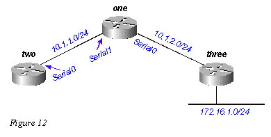
Router One has a static route to the network 172.16.1.0/24 configured through interface Serial 0:
ip route 172.16.1.0 255.255.255.0 Serial0
And Router One also has a network statement for the destination of this static route:
router eigrp 2000
network 10.0.0.0
network 172.16.0.0
no auto-summaryRouter One redistributes this route, even though it is not redistributing static routes, because EIGRP considers this a directly attached network. On Router Two, this looks as follows:
two# show ip route
….
10.0.0.0/8 is variably subnetted, 2 subnets, 2 masks
C 10.1.1.0/24 is directly connected, Serial0
D 10.1.2.0/24 [90/2169856] via 10.1.1.1, 00:00:47, Serial0
172.16.0.0/24 is subnetted, 1 subnets
D 172.16.1.0 [90/2169856] via 10.1.1.1, 00:00:47, Serial0Note the route to 172.16.1.0/24 appears as an internal EIGRP route on Router Two.
Summarization
There are two forms of summarization in EIGRP: auto-summaries and manual summaries.
Auto-Summarization
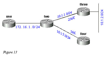
EIGRP performs an auto-summarization each time it crosses a border between two different major networks. For example, in Figure 13, Router Two advertises only the 10.0.0.0/8 network to Router One, because the interface Router Two uses to reach Router One is in a different major network.
On Router One, this looks like the following:
one# show ip eigrp topology 10.0.0.0
IP-EIGRP topology entry for 10.0.0.0/8
State is Passive, Query origin flag is 1, 1 Successor(s), FD is 11023872
Routing Descriptor Blocks:
172.16.1.1 (Serial0), from 172.16.1.2, Send flag is 0x0
Composite metric is (11023872/10511872), Route is Internal
Vector metric:
Minimum bandwidth is 256 Kbit
Total delay is 40000 microseconds
Reliability is 255/255
Load is 1/255
Minimum MTU is 1500
Hop count is 1This route is not marked as a summary route in any way; it looks like an internal route. The metric is the best metric from among the summarized routes. Note that the minimum bandwidth on this route is 256k, although there are links in the 10.0.0.0 network that have a bandwidth of 56k.
On the router doing the summarization, a route is built to null0 for the summarized address:
two# show ip route 10.0.0.0
Routing entry for 10.0.0.0/8, 4 known subnets
Attached (2 connections)
Variably subnetted with 2 masks
Redistributing via eigrp 2000C 10.1.3.0/24 is directly connected, Serial2
D 10.1.2.0/24 [90/10537472] via 10.1.1.2, 00:23:24, Serial1
D 10.0.0.0/8 is a summary, 00:23:20, Null0
C 10.1.1.0/24 is directly connected, Serial1The route to 10.0.0.0/8 is marked as a summary through Null0. The topology table entry for this summary route looks like the following:
two# show ip eigrp topology 10.0.0.0
IP-EIGRP topology entry for 10.0.0.0/8
State is Passive, Query origin flag is 1, 1 Successor(s), FD is 10511872
Routing Descriptor Blocks:
0.0.0.0 (Null0), from 0.0.0.0, Send flag is 0x0
(note: the 0.0.0.0 here means this route is originated by this router)
Composite metric is (10511872/0), Route is Internal
Vector metric:
Minimum bandwidth is 256 Kbit
Total delay is 20000 microseconds
Reliability is 255/255
Load is 1/255
Minimum MTU is 1500
Hop count is 0To make Router Two advertise the components of the 10.0.0.0 network instead of a summary, configure no auto-summary on the EIGRP process on Router Two:
On Router Two
router eigrp 2000
network 172.16.0.0
network 10.0.0.0
no auto-summaryWith auto-summary turned off, Router One now sees all of the components of the 10.0.0.0 network:
one# show ip eigrp topology
IP-EIGRP Topology Table for process 2000Codes: P – Passive, A – Active, U – Update, Q – Query, R – Reply,
r – Reply statusP 10.1.3.0/24, 1 successors, FD is 46354176
via 20.1.1.1 (46354176/45842176), Serial0
P 10.1.2.0/24, 1 successors, FD is 11049472
via 20.1.1.1 (11049472/10537472), Serial0
P 10.1.1.0/24, 1 successors, FD is 11023872
via 20.1.1.1 (11023872/10511872), Serial0
P 172.16.1.0/24, 1 successors, FD is 2169856There are some caveats when dealing with the summarization of external routes that are covered later in the Auto-Summarization of External Routes section.
Manual Summarization
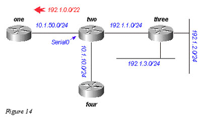
EIGRP allows you to summarize internal and external routes on virtually any bit boundary using manual summarization. For example, in Figure 14, Router Two is summarizing the 192.1.1.0/24, 192.1.2.0/24, and 192.1.3.0/24 into the CIDR block 192.1.0.0/22.
The configuration on Router Two is shown below:
two# show run
….
!
interface Serial0
ip address 10.1.50.1 255.255.255.0
ip summary-address eigrp 2000 192.1.0.0 255.255.252.0
no ip mroute-cache
!
….two# show ip eigrp topology
IP-EIGRP Topology Table for process 2000
Codes: P – Passive, A – Active, U – Update, Q – Query, R – Reply,
r – Reply statusP 10.1.10.0/24, 1 successors, FD is 45842176
via Connected, Loopback0
P 10.1.50.0/24, 1 successors, FD is 2169856
via Connected, Serial0
P 192.1.1.0/24, 1 successors, FD is 10511872
via Connected, Serial1
P 192.1.0.0/22, 1 successors, FD is 10511872
via Summary (10511872/0), Null0
P 192.1.3.0/24, 1 successors, FD is 10639872
via 192.1.1.1 (10639872/128256), Serial1
P 192.1.2.0/24, 1 successors, FD is 10537472
via 192.1.1.1 (10537472/281600), Serial1Note the ip summary-address command under interface Serial0, and the summary route via Null0. On Router One, we see this as an internal route:
one# show ip eigrp topology
IP-EIGRP Topology Table for process 2000Codes: P – Passive, A – Active, U – Update, Q – Query, R – Reply,
r – Reply statusP 10.1.10.0/24, 1 successors, FD is 46354176
via 10.1.50.1 (46354176/45842176), Serial0
P 10.1.50.0/24, 1 successors, FD is 2169856
via Connected, Serial0
P 192.1.0.0/22, 1 successors, FD is 11023872
via 10.1.50.1 (11023872/10511872), Serial0Auto-Summarization of External Routes
EIGRP will not auto-summarize external routes unless there is a component of the same major network that is an internal route. To illustrate, let us look at Figure 15.
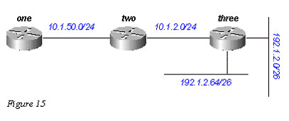
Router Three is injecting external routes to 192.1.2.0/26 and 192.1.2.64/26 into EIGRP using the redistribute connected command, as shown in the configurations below.
Router Three
interface Ethernet0
ip address 192.1.2.1 255.255.255.192
!
interface Ethernet1
ip address 192.1.2.65 255.255.255.192
!
interface Ethernet2
ip address 10.1.2.1 255.255.255.0
!router eigrp 2000
redistribute connected
network 10.0.0.0
default-metric 10000 1 255 1 1500With this configuration on Router Three, the routing table on Router One shows:
one# show ip route
….
10.0.0.0/8 is subnetted, 2 subnets
D 10.1.2.0 [90/11023872] via 10.1.50.2, 00:02:03, Serial0
C 10.1.50.0 is directly connected, Serial0
192.1.2.0/26 is subnetted, 1 subnets
D EX 192.1.2.0 [170/11049472] via 10.1.50.2, 00:00:53, Serial0
D EX 192.1.2.64 [170/11049472] via 10.1.50.2, 00:00:53, Serial0Although auto-summary normally causes Router Three to summarize the 192.1.2.0/26 and 192.1.2.64/26 routes into one major net destination (192.1.2.0/24), it does not do this because both routes are external. However, if you reconfigure the link between Routers Two and Three to 192.1.2.128/26, and add network statements for this network on Routers Two and Three, the 192.1.2.0/24 auto-summary is then generated on Router Two.
Router Three
interface Ethernet0
ip address 192.1.2.1 255.255.255.192
!
interface Ethernet1
ip address 192.1.2.65 255.255.255.192
!
interface Serial0
ip address 192.1.2.130 255.255.255.192
!
router eigrp 2000
network 192.1.2.0Now Router Two generates the summary for 192.1.2.0/24:
two# show ip route
….
D 192.1.2.0/24 is a summary, 00:06:48, Null0
….
And Router One shows only the summary route:one# show ip route
….
10.0.0.0/8 is subnetted, 1 subnets
C 10.1.1.0 is directly connected, Serial0
D 192.1.2.0/24 [90/11023872] via 10.1.50.2, 00:00:36, Serial0Query Processing and Range
When a router processes a query from a neighbor, the following rules apply:
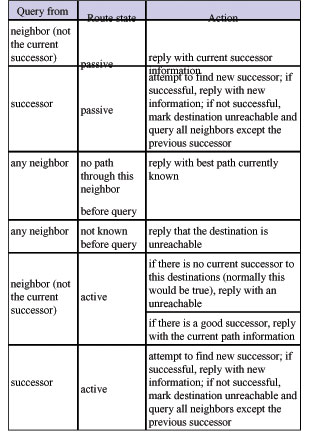
The actions in the table above impact the range of the query in the network by determining how many routers receive and reply to the query before the network converges on the new topology. To see how these rules affect the way queries are handled, let us look at the network in Figure 16, which is running under normal conditions.
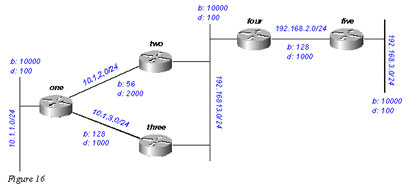
We can expect the following to happen regarding network 192.168.3.0/24 (far right side):
- Router One has two paths to 192.168.3.0/24:
through Router Two with a distance of 46533485 and a reported distance of 20307200
through Router Three with a distance of 20563200 and a reported distance of 20307200 - Router One chooses the path through Router Three and keeps the path through Router Two as a feasible successor
- Routers Two and Three show one path to 192.168.3.0/24 through Router Four
Suppose that 192.168.3.0/24 fails. What activity can we expect to see on this network? Figures 16a through 16h illustrate the process.
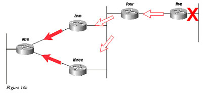
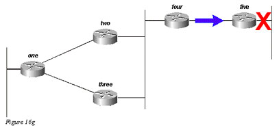
Router Five marks 192.168.3.0/24 as unreachable, and queries Router Four:
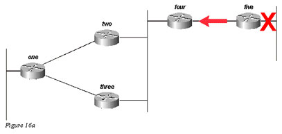
Router Four, upon receiving a query from its successor, attempts to find a new feasible successor to this network. It does not find one, so it marks 192.168.3.0/24 as unreachable and query Routers Two and Three:
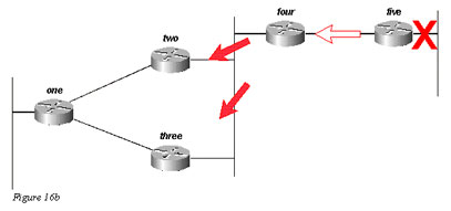
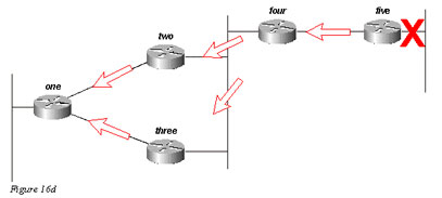
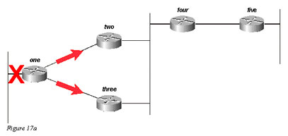
Routers Two and Three, in turn, see that they have lost their only feasible route to 192.168.3.0/24, and mark it as unreachable; they both send queries to Router One:
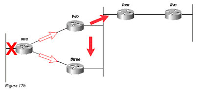
For simplicity, let us assume that Router One receives the query from Router Three first, and marks the route as unreachable. Router One then receives the query from Router Two. Although another order is possible, they will all have the same final result.
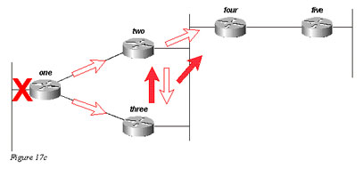
Router One replies to both queries with unreachables; Router One is now passive for 192.168.3.0/24:
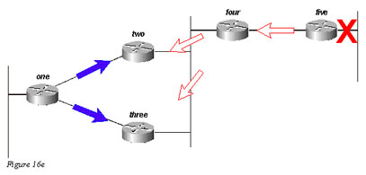
Routers Two and Three reply to the query from Router Four; Routers Two and Three are now passive for 192.168.3.0/24:
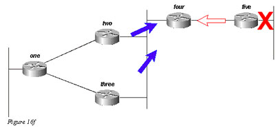
Router Five, upon receiving the reply from Router Four, removes network 192.168.3.0/24 from its routing table; Router Five is now passive for network 192.168.3.0/24. Router Five sends updates back to Router Four so the route is removed from the topology and routing tables of the remaining routers.
It is important to understand that although there may be other query paths or processing orders, all routers in the network process a query for network 192.168.3.0/24 when that link goes down. Some routers may end up processing more than one query (Router One in this example). In fact, if the queries were to reach the routers in a different order, some would end up processing three or four queries. This is a good example of an unbounded query in an EIGRP network.
How Summarization Points Affect the Query Range
Now let us look at the paths to 10.1.1.0/24 in the same network:
- Router Two has a topology table entry for the 10.1.1.0/24 network with a cost of 46251885 through Router One.
- Router Three has a topology table entry for the 10.1.1.0/24 network with a cost of 20281600 through Router One.
- Router Four has a topology table entry for the 10.0.0.0/8 network (because Routers Two and Three are autosummarizing to the major network boundary) through Router Three with a metric of 20307200 (the reported distance through Router Two is higher than the total metric through Router Three, so the path through Router Two is not a feasible successor).

If 10.1.1.0/24 goes down, Router One marks it as unreachable, and then queries each of its neighbors (Routers Two and Three) for a new path to that network:
Router Two, on receiving the query from Router One, marks the route as unreachable (because the query is from its successor) and then queries Routers Four and Three:
Router Three, when it receives the query from Router One, marks the destination as unreachable and queries Routers Two and Four:
Router Four, when it receives the queries from Routers Two and Three, replies that 10.1.1.0/24 is unreachable (note that Router Four has no knowledge of the subnet in question, since it only has the 10.0.0.0/8 route):

Routers Two and Three reply to each other that 10.1.1.0/24 is unreachable:
Since Routers Two and Three now have no outstanding queries, they both reply to Router One that 10.1.1.0/24 is unreachable:
The query, in this case, is bounded by the autosummarization at Routers Two and Three. Router Five does not participate in the query process, and is not involved in the re-convergence of the network. Queries can also be bound by manual summarization, autonomous system borders, and distribution lists.
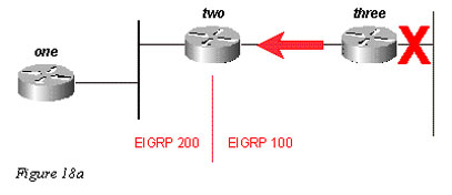
How Autonomous System Boundaries Affect the Query Range
If a router is redistributing routes between two EIGRP autonomous systems, it replies to the query within the normal processing rules and launches a new query into the other autonomous system. For example, if the link to the network attached to Router Three goes down, Router Three marks the route unreachable and queries Router Two for a new path:
Router Two replies that this network is unreachable and launches a query into autonomous system 200 toward Router One. Once Router Three receives the reply to its original query, it removes the route from its table. Router Three is now passive for this network:
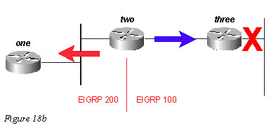
Router One replies to Router Two, and the route goes passive:
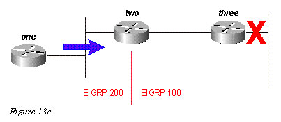
While the original query did not propagate throughout the network (it was bound by the autonomous system border), the original query leaks into the second autonomous system in the form of a new query. This technique may help to prevent stuck in active (SIA) problems in a network by limiting the number of routers a query must pass through before being answered, but it does not solve the overall problem that each router must process the query. In fact, this method of bounding a query may worsen the problem by preventing the auto-summarization of routes that would otherwise be summarized (external routes are not summarized unless there is an external component in that major network).
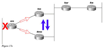
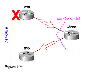
How Distribution Lists Affect the Query Range
Rather than block the propagation of a query, distribution lists in EIGRP mark any query reply as unreachable. Let us use Figure 19 as an example.
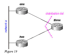
In the figure above:
- Router Three has a distribute-list applied against its serial interfaces that only permits it to advertise Network B.
- Routers One and Two do not know that Network A is reachable through Router Three (Router Three is not used as a transit point between Routers One and Two).
- Router Three uses Router One as its preferred path to Network A, and does not use Router Two as a feasible successor.
When Router One loses its connection to Network A, it marks the route as unreachable and sends a query to Router Three. Router Three does not advertise a path to Network A because of the distribution list on its serial ports.
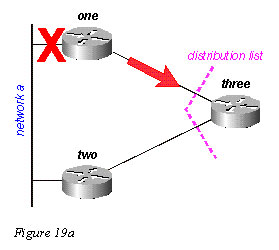
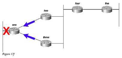
Router Three marks the route as unreachable, then queries Router Two:
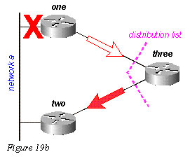
Router Two examines its topology table and finds that it has a valid connection to Network A. Note the query was not affected by the distribution list in Router Three:
Router Two replies that Network A is reachable; Router Three now has a valid route:
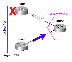
Router Three builds the reply to the query from Router One, but the distribution list causes Router Three to send a reply that Network A is unreachable, even though Router Three has a valid route to Network A:
I hope you found this article to be of use and it helps you prepare for your Cisco CCNA certification. Achieving your CCNA certification is much more than just memorizing Cisco exam material. It is having the real world knowledge to configure your Cisco equipment and be able to methodically troubleshoot Cisco issues. So I encourage you to continue in your studies for your CCNA exam certification.