|
|
| Frame Relay Overview |
| |
|
In preparation of our CCNA exam, we want to make sure we cover the various concepts that we could see on our Cisco CCNA exam. So to assist you, below we will discuss Frame Relay Overview.
|
| Frame Relay is a connection-oriented Layer 2 protocol that allows several data connections(called virtual circuits) to be multiplexed onto a single physical link. Frame Relay relies on upper-layer protocols for error correction. Frame Relay specifies only the connection between a router and a service provider’s local access switching equipment. The data transmission within the service provider’s Frame Relay cloud is not specified. A connection identifier is used to map packets to outbound ports on the service provider’s switch. When the switch receives a frame, a lookup table is used to map the frame to the correct outbound port. The entire path to the destination is determined before the frame is sent. |
| |
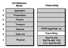
| Frame Relay Stack |
| |
| Most Frame Relay functions exist at the lower two layers of the OSI Reference Model. Frame Relay is supported on the same physical serial connections that support point-to-point connections. Cisco routers support the following serial connections: EIA/TIA-232, EIA/TIA-449, V.35, X.21, EIA/TIA-530. Upper-layer information (such as IP data) is encapsulated by Frame Relay and is transmitted over the link. |
| |
 |
| |
| Frame Relay Terms |
|
|
BECN (Backward Explicit Congestion Notification)—A message sent to a source router when a Frame Relay switch recognizes congestion in the network. A BECN message requests a reduced data transmission rate. |
|
|
CIR (Committed Information Rate)—The minimum guaranteed data transfer rate agreed to by the Frame Relay switch. |
|
|
DLCI (Data Link Connection Identifier)—Identifies the logical circuit between the router and the Frame Relay switch. |
|
|
FECN (Forward Explicit Congestion Notification)—A message sent to a destination device when a Frame Relay switch senses congestion in the network. |
|
|
Inverse ARP—Routers use Inverse ARP to discover the network address of a device associated with a VC. |
|
|
LMI (Local Management Interface)—A signaling standard used to manage the connection between the router and the Frame Relay switch. LMIs track and manage keepalive mechanisms, multicast messages, and status. LMI can be configured (in Cisco IOS 11.2 and later), but routers can autosense LMI types by sending a status request to the Frame Relay switch. The router configures itself to match the LMI type response. The three types of LMIs supported by Cisco Frame Relay switches are Cisco (developed by Cisco, StrataCom, Northern Telecom, and DEC), ansi Annex D (ANSI standard T1.617), and q933a (ITU-T Q.933 Annex A). |
|
|
VC (virtual circuit)—A logical circuit between two network devices. A VC can be permanent (PVC) or switched (SVC). PVCs save bandwidth (there is no circuit establishment or teardown) but can be expensive. SVCs are established on-demand and are torn down when transmission is complete. VC status can be active, inactive, or deleted. |
|
| |
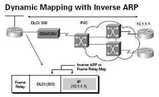
| Dynamic Mapping with Inverse ARP |
| |
| To correctly route packets, each DLCI must be mapped to a nexthop address. These addresses can be dynamically mapped using Inverse ARP or can be manually configured. After the address is mapped, it is stored in the router’s Frame Relay map table. |
| |
 |
| |
| LMI Signaling Process |
| 1 |
The router connects to a Frame Relay switch through a channel service unit/data service unit (CSU/DSU). |
| 2 |
The router sends a VC status inquiry to the Frame Relay switch. |
| 3 |
The switch responds with a status message that includes the DLCI’s information for the usable PVCs. |
| 4 |
The router advertises itself by sending an Inverse ARP to each active DLCI. |
| 5 |
The routers create map entries with the local DLCI and network-layer address of the remote routers. Static maps must be configured if Inverse ARP is not supported. |
| 6 |
Inverse ARP messages are sent every 60 seconds. |
| 7 |
LMI information is exchanged every 10 seconds. |
|
| |
| Frame Relay Overview Summary |
|
|
Frame Relay is a connection-oriented Layer 2 protocol that allows several data connections (VCs) to be multiplexed onto a single physical link. |
|
|
Cisco routers support Frame Relay on the following types of serial connections: EIA/TIA-232, EIA/TIA-449, V.35, X.21, and EIA/TIA-530. |
|
|
Local DLCI addresses can be dynamically mapped using Inverse ARP or manually configured using static Frame Relay maps. |
|
|
Local Management Interface (LMI) signaling is used by Frame Relay switches to manage connections and maintain status between the devices. The supported LMI types are cisco, ansi, and q933a. |
|
| |
| Continue on to the Frame Relay Configuration Article |
We hope you found this Cisco certification article helpful. We pride ourselves on not only providing top notch Cisco CCNA exam information, but also providing you with the real world Cisco CCNA skills to advance in your networking career.
| |