HDLC: High Level Data Link Control
In preparation of our CCNA exam, we want to make sure we cover the various concepts that we could see on our Cisco CCNA exam. So to assist you, below we will discuss an HDLC Overview.
The Camtasia Studio video content presented here requires JavaScript to be enabled and the latest version of the Adobe Flash Player. If you are you using a browser with JavaScript disabled please enable it now. Otherwise, please update your version of the free Adobe Flash Player by downloading here.
The High Level Data Link Control (HDLC) protocol, an ISO data link layer protocol based on the IBM SDLC, is to ensure that data passed up to the next layer has been received exactly as transmitted (i.e error free, without loss and in the correct order). Another important function of HDLC is flow control, which ensures that data is transmitted only as fast as the receiver can receive it. There are two distinct HDLC implementations: HDLC NRM (also known as SDLC) and HDLC Link Access Procedure Balanced (LAPB), the later is a more popular implementation. HDLC is usually used by X.25.
LAPB is a bit-oriented synchronous protocol that provides complete data transparency in a full-duplex point-to-point operation. It supports a peer-to-peer link in that neither end of the link plays the role of the permanent master station. HDLC NRM, on the other hand, has a permanent primary station with one or more secondary stations.
HDLC LAPB is a very efficient protocol, which requires a minimum of overhead to ensure flow control, error detection and recovery. If data is flowing in both directions (full duplex), the data frames themselves carry all the information required to ensure data integrity.
The concept of a frame window is used to send multiple frames before receiving confirmation that the first frame has been correctly been received. This means that data can continue to flow in situations where there may be long “turn-around” time lags without stopping to wait for an acknowledgement. This kind of situation occurs, for instance in satellite communication.
There are three categories of frames:/p>
- Information framestransport data across the link and may encapsulate the higher layers of the OSI architecture.
- Supervisory framesperform the flow control and error recovery functions.
- Unnumbered framesprovide the link initialization and termination.
Protocol Structure – HDLC: High Level Data Link Control
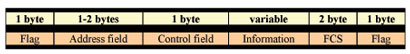
Flag – The value of the flag is always (0x7E).
Address field – Defines the address of the secondary station which is sending the frame or the destination of the frame sent by the primary station. It contains Service Access Point (6bits), a Command/Response bit to indicate whether the frame relates to information frames (I-frames) being sent from the node or received by the node, and an address extension bit which is usually set to true to indicate that the address is of length one byte. When set to false it indicates an additional byte follows.
Extended address – HDLC provides another type of extension to the basic format. The address field may be extended to more than one byte by agreement between the involved parties.
Control field – Serves to identify the type of the frame. In addition, it includes sequence numbers, control features and error tracking according to the frame type.
FCS – The Frame Check Sequence (FCS) enables a high level of physical error control by allowing the integrity of the transmitted frame data to be checked.
I hope you found this article to be of use and it helps you prepare for your Cisco CCNA certification. I am sure you will quickly find out that hands-on real world experience is the best way to cement the CCNA concepts in your head to help you pass your CCNA exam!