In preparation of your CCNA exam, we want to make sure we cover the various concepts that we could see on your Cisco CCNA exam. So to assist you, below we will discuss one of the more difficult CCNA concepts, Spanning-Tree Protocol. As you progress through your CCNA exam studies, I am sure with repetition you will find this topic becomes easier. So even though it may be a difficult concept and confusing at first, keep at it as no one said getting your Cisco certification would be easy!
STP Basics
Supported STP Instances
This software release supports the per-VLAN spanning tree (PVST) and a maximum of 64 spanning-tree instances. If more VLANs are defined in the VLAN Trunking Protocol (VTP) than STP instances, you can enable STP on only 64 VLANs. The remaining VLANs operate with STP disabled.
If 64 instances of STP are already in use, you can disable STP on one of the VLANs and then enable it on the VLAN where you want it to run. Use the no spanning-tree vlan vlan-id global configuration command to disable STP on a specific VLAN, and use the spanning-tree vlan vlan-id global configuration command to enable STP on the desired VLAN.
Caution Switches that are not running STP still forward Bridge Protocol Data Units (BPDUs) that they receive so that the other switches on the VLAN that have a running spanning-tree instance can break loops. Therefore, STP must be running on enough switches to break all the loops in the network; for example, at least one switch on each loop in the VLAN must be running STP. It is not absolutely necessary to run STP on all switches in the VLAN; however, if you are running STP only on a minimal set of switches, an incautious change to the network that introduces another loop into the VLAN can result in a broadcast storm.
Note If you have already used all available spanning-tree instances on your switch, adding another VLAN anywhere in the VTP domain creates a VLAN that is not running STP on that switch. If you have the default allowed list on the trunk ports of that switch, the new VLAN is carried on all trunk ports. Depending on the topology of the network, this could create a loop in the new VLAN that will not be broken, particularly if there are several adjacent switches that have all run out of spanning-tree instances. You can prevent this possibility by setting allowed lists on the trunk ports of switches that have used up their allocation of spanning-tree instances. Setting up allowed lists is not necessary in many cases and can make it more labor-intensive to add another VLAN to the network.
Spanning-tree commands determine the configuration of VLAN spanning-tree instances. You create a spanning-tree instance when you assign an interface to a VLAN. The spanning-tree instance is removed when the last interface is moved to another VLAN. You can configure switch and port parameters before an spanning-tree instance is created; these parameters are applied when the spanning-tree instance is created.
STP Overview
STP is a link management protocol that provides path redundancy while preventing undesirable loops in the network. For an Ethernet network to function properly, only one active path can exist between any two stations. STP operation is transparent to end stations, which cannot detect whether they are connected to a single LAN segment or a switched LAN of multiple segments.
When you create fault-tolerant internetworks, you must have a loop-free path between all nodes in a network. The spanning-tree algorithm calculates the best loop-free path throughout a switched network. Switches send and receive STP frames at regular intervals. The switches do not forward these frames, but use the frames to construct a loop-free path.
Multiple active paths between end stations cause loops in the network. If a loop exists in the network, end stations might receive duplicate messages. Switches might also learn end-station MAC addresses on multiple interfaces. These conditions result in an unstable network.
STP defines a tree with a root switch and a loop-free path from the root to all switches in the network. STP forces redundant data paths into a standby (blocked) state. If a network segment in the spanning tree fails and a redundant path exists, the spanning-tree algorithm recalculates the spanning-tree topology and activates the standby path.
When two interfaces on a switch are part of a loop, the STP port priority and path cost settings determine which interface is put in the forwarding state and which is put in the blocking state. The STP port priority value represents the location of an interface in the network topology and how well it is located to pass traffic. The STP path cost value represents media speed.
Election of the Root Switch
All switches in the network participating in STP gather information about other switches in the network through an exchange of data messages called Bridge Protocol Data Units (BPDUs). This exchange of messages results in these actions:
- The election of a unique root switch for each instance of spanning tree
- The election of a designated switch for every switched LAN segment
- The removal of loops in the switched network by blocking interfaces connected to redundant links
For each VLAN, the switch with the highest switch priority (the lowest numerical priority value) is elected as the root switch. If all switches are configured with the default priority (32768), the switch with the lowest MAC address in the VLAN becomes the root switch.
The spanning-tree root switch is the logical center of the STP topology in a switched network. All paths that are not needed to reach the root switch from anywhere in the switched network are placed in STP blocking mode.
BPDUs contain information about the transmitting switch and its ports, including switch and MAC addresses, switch priority, port priority, and path cost. STP uses this information to elect the root switch and root port for the switched network, as well as the root port and designated port for each switched segment.
Bridge Protocol Data Units
The stable, active STP topology of a switched network is determined by these elements:
- The unique bridge ID (switch priority and MAC address) associated with each VLAN on each switch
- The STP path cost to the root switch
- The port identifier (port priority and MAC address) associated with each interface
The BPDUs are transmitted in one direction from the root switch, and each switch sends configuration BPDUs to communicate and to compute the STP topology. Each configuration BPDU contains this information:
- The unique bridge ID of the switch that the transmitting switch identifies as the root switch
- The STP path cost to the root
- The bridge ID of the transmitting switch
- Message age
- The identifier of the transmitting interface
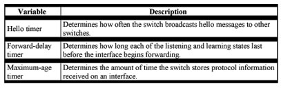
- Values for the hello, forward delay, and max-age protocol timers
When a switch transmits a BPDU frame, all switches connected to the LAN on which the frame is transmitted receive the BPDU. When a switch receives a BPDU, it does not forward the frame but instead uses the information in the frame to calculate a BPDU, and, if the topology changes, initiates a BPDU transmission.
A BPDU exchange results in these actions:
- One switch is elected as the root switch.
- The shortest distance to the root switch is calculated for each switch based on the path cost.
- A designated switch for each LAN segment is selected. The designated switch is the one closest to the root switch through which frames are forwarded to the root.
- A root port is selected. This port provides the best path from the switch to the root switch.
- Interfaces included in the spanning-tree instance are selected.
- All interfaces not included in the spanning tree are blocked.
STP Timers
Table 9-1 describes the STP timers that affect the entire spanning-tree performance.
Creating the STP Topology
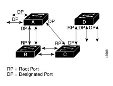
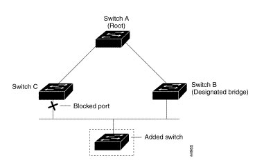
In Figure 9-1, Switch A is elected as the root switch because the switch priority of all the switches is set to the default (32768) and Switch A has the lowest MAC address.
However, due to traffic patterns, number of forwarding interfaces, or link types, Switch A might not be the ideal root switch. By increasing the priority (lowering the numerical value) of the ideal switch so that it becomes the root switch, you force an STP recalculation to form a new topology with the ideal switch as the root.
Figure 9-1 STP Topology
When the spanning-tree topology is calculated based on default parameters, the path between source and destination end stations in a switched network might not be ideal. For instance, connecting higher-speed links to an interface that has a higher number than the current root port can cause a root-port change. The goal is to make the fastest link the root port.
For example, assume that one port on Switch B is a Gigabit Ethernet link and that another port on
Switch B (a 10/100 link) is the root port. Network traffic might be more efficient over the Gigabit Ethernet link. By changing the STP port priority on the Gigabit Ethernet interface to a higher priority (lower numerical value) than the root port, the Gigabit Ethernet interface becomes the new root port.
STP Interface States
Propagation delays can occur when protocol information passes through a switched LAN. As a result, topology changes can take place at different times and at different places in a switched network. When a interface transitions directly from nonparticipation in the spanning-tree topology to the forwarding state, it can create temporary data loops. Interfaces must wait for new topology information to propagate through the switched LAN before starting to forward frames. They must allow the frame lifetime to expire for forwarded frames that have used the old topology.
Each interface on a switch using STP exists in one of these states:
- Blocking—The interface does not participate in frame forwarding.
- Listening—The first transitional state after the blocking state when STP determines that the interface should participate in frame forwarding.
- Learning—The interface prepares to participate in frame forwarding.
- Forwarding—The interface forwards frames.
- Disabled—The interface is not participating in STP because of a shutdown port, no link on the port, or no spanning-tree instance running on the port.
An interface moves through these states:
- From initialization to blocking
- From blocking to listening or to disabled
- From listening to learning or to disabled
- From learning to forwarding or to disabled
- From forwarding to disabled
Figure 9-2 illustrates how an interface moves through the states.
Figure 9-2 Spanning Tree Interface States
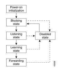
When you power up the switch, STP is enabled by default, and every interface in the switch, VLAN, or network goes through the blocking state and the transitory states of listening and learning. Spanning tree stabilizes each interface at the forwarding or blocking state.
When the spanning-tree algorithm places an interface in the forwarding state, this process occurs:
- The interface is put in the listening state while spanning tree waits for protocol information to transition the interface to the blocking state.
- While spanning tree waits for the forward-delay timer to expire, it moves the interface to the learning state and resets the forward-delay timer.
- In the learning state, the interface continues to block frame forwarding as the switch learns end-station location information for the forwarding database.
- When the forward-delay timer expires spanning tree moves the interface to the forwarding state, where both learning and frame forwarding are enabled.
Blocking State
An interface in the blocking state does not participate in frame forwarding. After initialization, a BPDU is sent to each interface in the switch. A switch initially functions as the root until it exchanges BPDUs with other switches. This exchange establishes which switch in the network is the root or root switch. If there is only one switch in the network, no exchange occurs, the forward-delay timer expires, and the interfaces move to the listening state. An interface always enters the blocking state following switch initialization.
An interface in the blocking state performs as follows:
- Discards frames received on the port
- Discards frames switched from another interface for forwarding
- Does not learn addresses
- Receives BPDUs
Listening State
The listening state is the first state an interface enters after the blocking state. The interface enters this state when STP determines that the interface should participate in frame forwarding.
An interface in the listening state performs as follows:
- Discards frames received on the port
- Discards frames switched from another interface for forwarding
- Does not learn addresses
- Receives BPDUs
Learning State
An interface in the learning state prepares to participate in frame forwarding. The interface enters the learning state from the listening state.
An interface in the learning state performs as follows:
- Discards frames received on the port
- Discards frames switched from another interface for forwarding
- Learns addresses
- Receives BPDUs
Forwarding State
An interface in the forwarding state forwards frames. The interface enters the forwarding state from the learning state.
An interface in the forwarding state performs as follows:
- Receives and forwards frames received on the port
- Forwards frames switched from another port
- Learns addresses
- Receives BPDUs
Disabled State
An interface in the disabled state does not participate in frame forwarding or STP. An interface in the disabled state is nonoperational.
A disabled interface performs as follows:
- Discards frames received on the port
- Discards frames switched from another interface for forwarding
- Does not learn addresses
- Does not receive BPDUs
MAC Address Allocation
The switch has a pool of MAC addresses, one for each instance of STP, that is used as the bridge IDs for the VLAN spanning-tree instances. MAC addresses are allocated sequentially.
STP Address Management
IEEE 802.1D specifies 17 multicast addresses, ranging from 0x00180C2000000 to 0x0180C2000010, to be used by different bridge protocols. These addresses are static addresses that cannot be removed.
Regardless of the STP state, the switch receives but does not forward packets destined for addresses between 0x0180c2000000 and 0x1080C200000F.
If STP is enabled, the switch CPU receives packets destined for 0x0180C2000000 and 0x0180C2000010. If STP is disabled, the switch forwards those packets as unknown multicast addresses.
STP and IEEE 802.1Q Trunks
The IEEE 802.1Q standard for VLAN trunks imposes some limitations on the spanningtree strategy for a network. The standard requires only one spanning-tree instance for all VLANs allowed on the trunks. However, in a network of Cisco switches connected through 802.1Q trunks, the switches maintain one spanning-tree instance for each VLAN allowed on the trunks.
When you connect a Cisco switch to a non-Cisco device through an 802.1Q trunk, the Cisco switch uses per-VLAN spanning tree+ (PVST+) to provide STP interoperability. It combines the spanning-tree instance of the 802.1Q VLAN of the trunk with the spanningtree instance of the non-Cisco 802.1Q switch.
However, all PVST+ information is maintained by Cisco switches separated by a cloud of non-Cisco 802.1Q switches. The non-Cisco 802.1Q cloud separating the Cisco switches is treated as a single trunk link between the switches.
PVST+ is automatically enabled on 802.1Q trunks, and no user configuration is required. The external spanning-tree behavior on access and port trunks is not affected by PVST+.
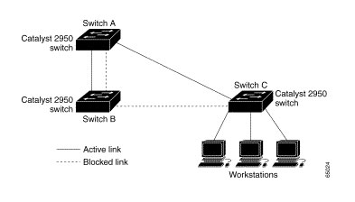
STP and Redundant Connectivity
You can create a redundant backbone with STP by connecting two switch interfaces to another device or to two different devices. STP automatically disables one interface but enables it if the other one fails, as shown in Figure 9-3. If one link is high-speed and the other is low-speed, the low-speed link is always disabled. If the speeds of the two links are the same, the port priority and port ID are added together, and STP disables the link with the lowest value.
Figure 9-3 STP and Redundant Connectivity
You can also create redundant links between switches by using EtherChannel groups.
Accelerated Aging to Retain Connectivity
The default for aging dynamic addresses is 5 minutes, the default setting of the macaddress- table aging-time global configuration command. However, an STP reconfiguration can cause many station locations to change. Because these stations could be unreachable for 5 minutes or more during a reconfiguration, the address-aging time is accelerated so that station addresses can be dropped from the address table and then relearned. The accelerated aging is the same as the forward-delay parameter value (spanning-tree vlan vlan-id forward-time seconds global configuration command) when STP reconfigures.
Because each VLAN is a separate spanning-tree instance, the switch accelerates aging on a per-VLAN basis. An STP reconfiguration on one VLAN can cause the dynamic addresses learned on that VLAN to be subject to accelerated aging. Dynamic addresses on other VLANs can be unaffected and remain subject to the aging interval entered for the switch.
Understanding Advanced STP Features
Understanding Port Fast
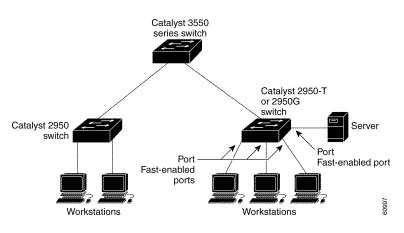
Port Fast immediately brings an interface configured as an access port to the forwarding state from a blocking state, bypassing the listening and learning states. You can use Port Fast on access ports connected to a single workstation or server, as shown in Figure 9-4, to allow those devices to immediately connect to the network, rather than waiting for STP to converge.
If the interface receives a BPDU, which should not happen if the interface is connected to a single workstation or server, STP puts the port in the blocking state. An interface with Port Fast enabled goes through the normal cycle of STP status changes when the switch is restarted.
Note Because the purpose of Port Fast is to minimize the time access ports must wait for STP to converge, it is effective only when used on access ports. If you enable Port Fast on a port connecting to another switch, you risk creating a spanning-tree loop.
Figure 9-4 Port Fast-Enabled Ports
Understanding BPDU Guard
When the BPDU guard feature is enabled on the switch, STP shuts down Port Fastenabled interfaces that receive BPDUs rather than putting them into the blocking state. In a valid configuration, Port Fast-enabled interfaces do not receive BPDUs. Receipt of a BPDU by a Port Fast-enabled interface means an invalid configuration, such as the connection of an unauthorized device, and the BPDU guard feature places the interface into the ErrDisable state. The BPDU guard feature provides a secure response to invalid configurations because you must manually put the interface back in service.
Note When enabled on the switch, STP applies the BPDU guard feature to all Port Fast-enabled interfaces.
Understanding UplinkFast
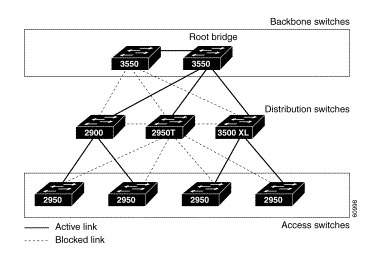
Switches in hierarchical networks can be grouped into backbone switches, distribution switches, and access switches. Figure 9-5 shows a complex network where distribution switches and access switches each have at least one redundant link that STP blocks to prevent loops.
Figure 9-5 Switches in a Hierarchical Network
If a switch looses connectivity, it begins using the alternate paths as soon as STP selects a new root port. When STP reconfigures the new root port, other interfaces flood the network with multicast packets, one for each address that was learned on the interface.
By using STP UplinkFast, you can accelerate the choice of a new root port when a link or switch fails or when STP reconfigures itself. The root port transitions to the forwarding state immediately without going through the listening and learning states, as it would with normal STP procedures. UplinkFast also limits the burst of multicast traffic by reducing the max-update-rate parameter (the default for this parameter is 150 packets per second). However, if you enter zero, station-learning frames are not generated, so the STP topology converges more slowly after a loss of connectivity.
Note UplinkFast is most useful in wiring-closet switches at the access or edge of the network. It is not appropriate for backbone devices. This feature might not be useful for other types of applications.
UplinkFast provides fast convergence after a direct link failure and achieves load balancing between redundant links using uplink groups. An uplink group is a set of interfaces (per VLAN), only one of which is forwarding at any given time. Specifically, an uplink group consists of the root port (which is forwarding) and a set of blocked ports, except for self-looping ports. The uplink group provides an alternate path in case the currently forwarding link fails.
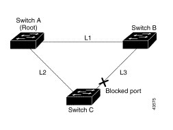
Figure 9-6 shows an example topology with no link failures. Switch A, the root switch, is connected directly to Switch B over link L1 and to Switch C over link L2. The interface on Switch C that is connected directly to Switch B is in a blocking state.
Figure 9-6 UplinkFast Example Before Direct Link Failure
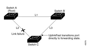
If Switch C detects a link failure on the currently active link L2 on the root port (a direct link failure), UplinkFast unblocks the blocked port on Switch C and transitions it to the forwarding state without going through the listening and learning states, as shown in Figure 9-7. This change takes approximately 1 to 5 seconds.
Figure 9-7 UplinkFast Example After Direct Link Failure
Understanding Cross-Stack UplinkFast
Cross-stack UplinkFast (CSUF) provides a fast spanning-tree transition (fast convergence in less than 1 second under normal network conditions) across a stack of switches that use the GigaStack GBICs connected in a shared cascaded configuration (multidrop backbone). During the fast transition, an alternate redundant link on the stack of switches is placed in the forwarding state without causing temporary spanning-tree loops or loss of connectivity to the backbone. With this feature, you can have a redundant and resilient network in some configurations.
CSUF might not provide a fast transition all the time; in these cases, the normal STP transition occurs, completing in 30 to 40 seconds.
How CSUF Works
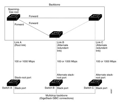
CSUF ensures that one link in the stack is elected as the path to the root. As shown in Figure 9-8, Switches A, B, and C are cascaded through the GigaStack GBIC to form a multidrop backbone, which communicates control and data traffic across the stack of switches at the access layer. The switches in the stack use their stack ports to communicate with each other and to connect to the stack backbone; stack ports are always in the STP forwarding state. The stack-root port on Switch A provides the path to the spanning-tree root; the alternate stack-root ports on Switches B and C can provide an alternate path to the spanning-tree root if the current stack-root switch fails or if its link to the spanning-tree root fails.
Link A, the root link, is in the STP forwarding state; Links B and C are alternate redundant links that are in the STP blocking state. If Switch A fails, if its stack- root port fails, or if Link A fails, CSUF selects either the Switch B or Switch C alternate stack root port and puts it into the forwarding state in less than 1 second.
Figure 9-8 Cross-Stack UplinkFast Topology
CSUF implements the Stack Membership Discovery Protocol and the Fast Uplink Transition Protocol. Using the Stack Membership Discovery Protocol, all stack switches build a neighbor list of stack members through the receipt of discovery hello packets. When certain link loss or STP events occur (described in “Events that Cause Fast Convergence” section), the Fast Uplink Transition Protocol uses the neighbor list to send fast-transition requests on the stack port to stack members.
The switch sending the fast-transition request needs to do a fast transition to the forwarding state of a port that it has chosen as the root port, and it must obtain an acknowledgement from each stack switch before performing the fast transition.
Each switch in the stack determines if the sending switch is a better choice than itself to be the stack root of this spanning-tree instance by comparing STP root, cost, and bridge ID. If the sending switch is the best choice as the stack root, each switch in the stack returns an acknowledgement; otherwise, it does not respond to the sending switch (drops the packet). The sending switch then has not received acknowledgements from all stack switches.
When acknowledgements are received from all stack switches, the Fast Uplink Transition Protocol on the sending switch immediately transitions its alternate stack-root port to the forwarding state. If acknowledgements from all stack switches are not obtained by the sending switch, the normal STP transitions (blocking, listening, learning, and forwarding) take place, and the spanning-tree topology converges at its normal rate (2 * forward-delay time + max-age time).
The Fast Uplink Transition Protocol is implemented on a per-VLAN basis and affects only one STP instance at a time.
Events that Cause Fast Convergence
Depending on the network event or failure, the CSUF fast convergence might or might not occur.
Fast convergence (less than 1 second under normal network conditions) occurs under these circumstances:
- The stack root port link fails.
If two switches in the stack have alternate paths to the root, only one of the switches performs the fast transition.
- The failed link, which connects the stack root to the STP root, recovers.
- A network reconfiguration causes a new stack root switch to be selected.
- A network reconfiguration causes a new port on the current stack root switch to be chosen as the stack root port.
Note The fast transition might not occur if multiple events occur simultaneously. For example, if a stack member switch is powered off, and at the same time, the link connecting the stack root to the STP root comes back up, the normal STP convergence occurs.
Normal STP convergence (30 to 40 seconds) occurs under these conditions:
- The stack root switch is powered off or the software failed.
- The stack root switch, which was powered off or failed, is powered on.
- A new switch, which might become the stack root, is added to the stack.
- A switch other than the stack root is powered off or failed.
- A link fails between stack ports on the multidrop backbone.
Limitations
These limitations apply to CSUF:
- CSUF uses the GigaStack GBIC and runs on Catalyst 3550 switches, all Catalyst 3500 XL switches, Catalyst 2950 switches with GBIC module slots, and on modular Catalyst 2900 XL switches.
- Up to nine stack switches can be connected through their stack ports to the multidrop backbone. Only one stack port per switch is supported.
- Each stack switch can be connected to the STP backbone through one uplink.
- If the stack consists of a mixture of Catalyst 2900 XL, Catalyst 3500 XL, Catalyst 2950 and Catalyst 3550 switches, up to 64 VLANs with STP enabled are supported. If the stack consists of Catalyst 3550 switches, up to 128 VLANs with STP enabled are supported.
Connecting the Stack Ports
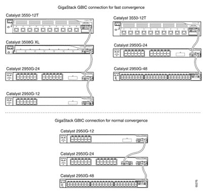
A fast transition occurs across the stack of switches if the multidrop backbone connections are a continuous link from one GigaStack GBIC to another as shown in Figure 9-9. You should follow these guidelines:
- A switch supports only one stack port.
- Do not connect alternate stack-root ports to stack ports.
- Connect all stack ports on the switch stack to the multidrop backbone.
- You can connect the open ports on the top and bottom GigaStack GBICs within the same stack to form a redundant link.
Figure 9-9 GigaStack GBIC Connections and STP Convergence
Understanding BackboneFast
BackboneFast is initiated when a root port or blocked port on a switch receives inferior BPDUs from its designated bridge. An inferior BPDU identifies one switch as both the root bridge and the designated bridge. When a switch receives an inferior BPDU, it means that a link to which the switch is not directly connected (an indirect link) has failed (that is, the designated bridge has lost its connection to the root switch). Under STP rules, the switch ignores inferior BPDUs for the configured maximum aging time specified by the spanning-tree max-age global configuration command.
The switch tries to determine if it has an alternate path to the root switch. If the inferior BPDU arrives on a blocked port, the root port and other blocked ports on the switch become alternate paths to the root switch. (Self-looped ports are not considered alternate paths to the root switch.) If the inferior BPDU arrives on the root port, all blocked ports become alternate paths to the root switch. If the inferior BPDU arrives on the root port and there are no blocked ports, the switch assumes that it has lost connectivity to the root switch, causes the maximum aging time on the root to expire, and becomes the root switch according to normal STP rules.
If the switch has alternate paths to the root switch, it uses these alternate paths to transmit a new kind of Protocol Data Unit (PDU) called the Root Link Query PDU. The switch sends the Root Link Query PDU on all alternate paths to the root switch. If the switch determines that it still has an alternate path to the root, it causes the maximum aging time on the ports on which it received the inferior BPDU to expire. If all the alternate paths to the root switch indicate that the switch has lost connectivity to the root switch, the switch causes the maximum aging times on the ports on which it received an inferior BPDU to expire. If one or more alternate paths can still connect to the root switch, the switch makes all ports on which it received an inferior BPDU its designated ports and moves them out of the blocking state (if they were in the blocking state), through the listening and learning states, and into the forwarding state.
Figure 9-10 shows an example topology with no link failures. Switch A, the root switch, connects directly to Switch B over link L1 and to Switch C over link L2. The interface on Switch C that connects directly to Switch B is in the blocking state.
Figure 9-10 BackboneFast Example Before Indirect Link Failure
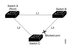
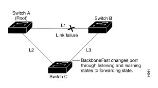
If link L1 fails, Switch C cannot detect this failure because it is not connected directly to link L1. However, because Switch B is directly connected to the root switch over L1, it detects the failure, elects itself the root, and begins sending BPDUs to Switch C, identifying itself as the root. When Switch C receives the inferior BPDUs from Switch B, Switch C assumes that an indirect failure has occurred. At that point, BackboneFast allows the blocked port on Switch C to move immediately to the listening state without waiting for the maximum aging time for the port to expire. BackboneFast then transitions the interface on Switch C to the forwarding state, providing a path from Switch B to Switch A. This switchover takes approximately 30 seconds, twice the Forward Delay time if the default Forward Delay time of 15 seconds is set. Figure 9-11 shows how BackboneFast reconfigures the topology to account for the failure of link L1.
Figure 9-11 BackboneFast Example After Indirect Link Failure
If a new switch is introduced into a shared-medium topology as shown in Figure 9-12, BackboneFast is not activated because the inferior BPDUs did not come from the recognized designated bridge (Switch B). The new switch begins sending inferior BPDUs that say it is the root switch. However, the other switches ignore these inferior BPDUs, and the new switch learns that Switch B is the designated bridge to Switch A, the root switch.
Figure 9-12 Adding a Switch in a Shared-Medium Topology
Understanding Root Guard
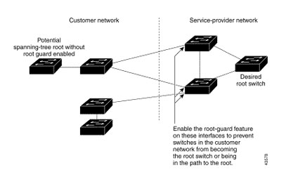
The network of a service provider (SP) can include many connections to switches that are not owned by the SP. In such a topology, STP can reconfigure itself and select a customer switch as the STP root switch, as shown in Figure 9-13. You can avoid this situation by configuring the root-guard feature on interfaces that connect to switches outside of your customer's network. If STP calculations cause an interface in the customer network to be selected as the root port, root guard then places the interface in the root-inconsistent (blocked) state to prevent the customer's switch from becoming the root switch or being in the path to the root.
If a switch outside the network becomes the root switch, the interface is blocked (rootinconsistent state), and STP selects a new root switch. The customer's switch does not become the root switch and is not in the path to the root.
Caution Misuse of the root-guard feature can cause a loss of connectivity.
Figure 9-13 STP in a Service Provider Network
Configuring Basic STP Features
These sections include basic STP configuration information:
Default STP Configuration
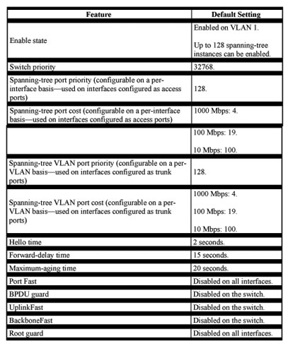
Table 9-2 shows the default STP configuration.
Table 9-2 Default STP Configuration
Disabling STP
STP is enabled by default on VLAN 1 and on all newly created VLANs up to the spanning-tree limit specified in Table 9-2. Disable STP only if you are sure there are no loops in the network topology.
Caution When STP is disabled and loops are present in the topology, excessive traffic and indefinite packet duplication can drastically reduce network performance.
Beginning in privileged EXEC mode, follow these steps to disable STP on a per-VLAN basis:
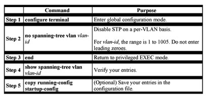
To re-enable STP, use the spanning-tree vlan vlan-id global configuration command.
Configuring the Root Switch
The switch maintains a separate spanning-tree instance for each active VLAN configured on it. A bridge ID, consisting of the switch priority and the switch MAC address, is associated with each instance. For each VLAN, the switch with the lowest bridge ID becomes the root switch for that VLAN.
To configure a switch to become the root, the switch priority can be modified from the default value (32768) to a significantly lower value so that the switch becomes the root switch for the specified VLAN. Use the spanning-tree vlan vlan-id root global configuration command to alter the switch priority. When you enter this command on a switch, it checks the switch priority of the current root switch for each VLAN and sets its own switch priority for the specified VLAN to 8192 if this value causes this switch to become the root for the specified VLAN. If any root switch for the specified VLAN has a switch priority lower than 8192, the switch sets its own priority for the specified VLAN to 1 less than the lowest switch priority.
For example, if all switches in the network have the switch priority for VLAN 100 set to the default value of 32768, entering the spanning-tree vlan 100 root primary global configuration command on a switch sets the switch priority for VLAN 100 to 8192, causing the switch to become the root switch for VLAN 100.
Note The root switch for each instance of STP should be a backbone or distribution switch. Do not configure an access switch as the spanning-tree primary root.
Use the diameter keyword to specify the network diameter (that is, the maximum number of switch hops between any two end stations in the network). When you specify the network diameter, the switch automatically sets an optimal hello time, forward-delay time, and maximum-age time for a network of that diameter, which can significantly reduce the convergence time. You can use the hello keyword to override the automatically calculated hello time.
Note We recommend that you avoid manually configuring the hello time, forwarddelay time, and maximum-age time after configuring the switch as the root switch.
Beginning in privileged EXEC mode, follow these steps to configure a switch as the root switch:
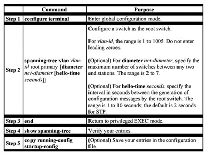
To return the switch to its default setting, use the no spanning-tree vlan vlan-id root global configuration command.
Configuring a Secondary Root Switch
When you configure a switch as the secondary root, the STP switch priority is changed from the default value (32768) to 16384 so that the switch is likely to become the root switch for the specified VLAN if the primary root switch fails (if the other switches in the network use the default switch priority of 32768, and therefore, are unlikely to become the root switch).
You can execute this command on more than one switch to configure multiple backup root switches. Use the same network diameter and hello-time values as you used when configuring the primary root switch.
Beginning in privileged EXEC mode, follow these steps to configure a switch as the secondary root switch:
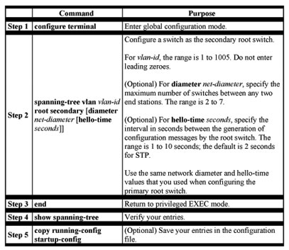
To return the switch to its default setting, use the no spanning-tree vlan vlan-id root global configuration command.
Configuring STP Port Priority
In the event of a loop, STP considers port priority when selecting an interface to put into the forwarding state. You can assign higher priority values (lower numerical values) to interfaces that you want selected first and lower priority values (higher numerical values) that you want selected last. If all interfaces have the same priority value, STP puts the interface with the lowest interface number in the forwarding state and blocks other interfaces. The priority range is 0 to 255; the default is 128.
Cisco IOS uses the port priority value when the interface is configured as an access port and uses VLAN port priority values when the interface is configured as a trunk port.
Beginning in privileged EXEC mode, follow these steps to configure the STP port priority of an interface:
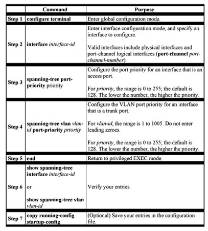
Note The show spanning-tree interface interface-id interface configuration command only displays information if the port is in a link-up operative state and is configured for Dynamic Trunking Protocol (DTP). Otherwise, you can use the show runningconfig interface interface configuration command to confirm the configuration.
To return the interface to its default setting, use the no spanning-tree vlan vlan-id portpriority interface configuration command.
Configuring STP Path Cost
The STP path cost default value is derived from the media speed of an interface. In the event of a loop, STP considers cost when selecting an interface to put in the forwarding state. You can assign lower cost values to interfaces that you want selected first and higher cost values that you want selected last. If all interfaces have the same cost value, STP puts the interface with the lowest interface number in the forwarding state and blocks other interfaces.
STP uses the cost value when the interface is configured as an access port and uses VLAN port cost values when the interface is configured as a trunk port.
Beginning in privileged EXEC mode, follow these steps to configure the STP cost of an interface:
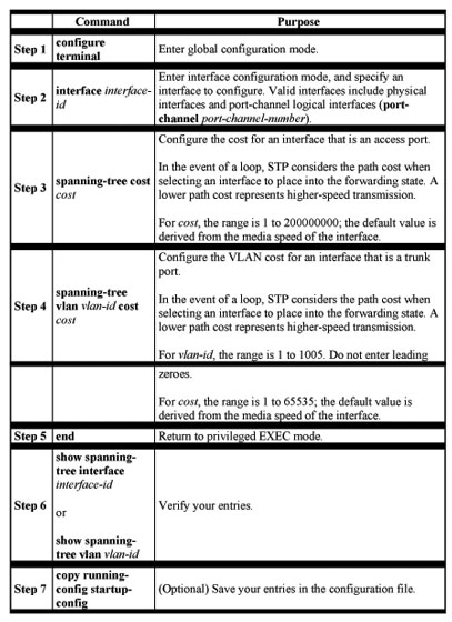
Note The show spanning-tree interface interface-id interface configuration command only displays information for ports that are in a link-up operative state and are configured for DTP. Otherwise, you can use the show running-config privileged EXEC command to confirm the configuration.
To return the interface to its default setting, use the no spanning-tree cost interface configuration or the no spanning-tree vlan vlan-id cost interface configuration command.
Configuring the Switch Priority of a VLAN
You can configure the switch priority and make it more likely that the switch will be chosen as the root switch.
Note Exercise care when using this command. For most situations, we recommend that you use the spanning-tree vlan vlan-id root primary and the spanning-tree vlan vlan-id root secondary global configuration commands to modify the switch priority.
Beginning in privileged EXEC mode, follow these steps to configure the STP switch priority of a VLAN:
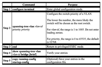
To return the switch to its default setting, use the no spanning-tree vlan vlan-id priority global configuration command.
Configuring the Hello Time
You can configure the interval between the generation of configuration messages by the root switch by changing the STP hello time.
Note Exercise care when using this command. For most situations, we recommend that you use the spanning-tree vlan vlan-id root primary and the spanning-tree vlan vlan-id root secondary global configuration commands to modify the hello time.
Beginning in privileged EXEC mode, follow these steps to configure the STP hello time of a VLAN:
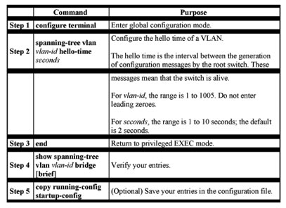
To return the switch to its default setting, use the no spanning-tree vlan vlan-id hellotime global configuration command.
Configuring the Forwarding-Delay Time for a VLAN
Beginning in privileged EXEC mode, follow these steps to configure the STP forwarding-delay time for a VLAN:
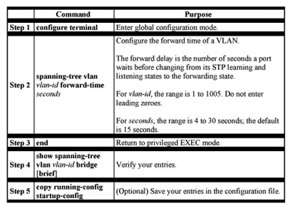
To return the switch to its default setting, use the no spanning-tree vlan vlan-id forward-time global configuration command.
Configuring the Maximum-Aging Time for a VLAN
Beginning in privileged EXEC mode, follow these steps to configure the STP maximumaging time for a VLAN:
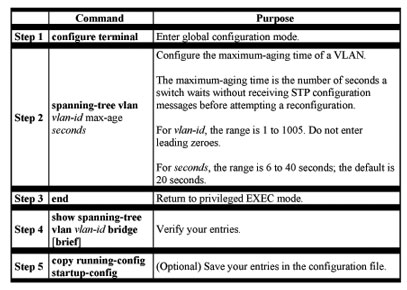
To return the switch to its default setting, use the no spanning-tree vlan vlan-id maxage global configuration command.
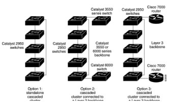
Configuring STP for Use in a Cascaded Cluster
STP uses default values that can be reduced when configuring your switch in cascaded configurations. If an STP root switch is part of a cluster that is one switch from a cascaded stack, you can customize STP to reconverge more quickly after a switch failure. Figure 9-14 shows switches in three cascaded clusters that use the GigaStack GBIC. Table 9-3 shows the default STP settings and those that are acceptable for these configurations.
Table 9-3 Default and Acceptable STP Parameter Settings (in seconds)
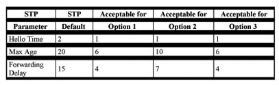
Figure 9-14 Gigabit Ethernet Clusters
Displaying STP Status
To display the current STP status, use one or more of the privileged EXEC commands in Table 9-4:
Table 9-4 Commands for Displaying STP Status
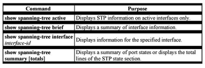
For information about other keywords for the show spanning-tree command, refer to the Catalyst 2950 Desktop Switch Command Reference for this release.
Configuring Advanced STP Features
Configuring Port Fast
A port with the Port Fast feature enabled is moved directly to the spanning-tree forwarding state without waiting for the standard forward-time delay.
Caution Use Port Fast only when connecting a single end station to an access port. Enabling this feature on an interface connected to a switch or hub could prevent STP from detecting and disabling loops in your network, which could cause broadcast storms and address-learning problems.
Beginning in privileged EXEC mode, follow these steps to enable Port Fast on an access port:
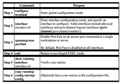
To disable the Port Fast feature, use the no spanning-tree portfast interface configuration command.
Configuring BPDU Guard
When the BPDU guard feature is enabled on the switch, STP shuts down Port Fastenabled interfaces that receive BPDUs rather than putting them into the blocking state.
Caution The BPDU guard feature works on Port Fast-enable interfaces. Configure Port Fast only on interfaces that connect to end stations; otherwise, an accidental topology loop could cause a data packet loop and disrupt switch and network operation.
Beginning in privileged EXEC mode, follow these steps to enable the BPDU guard feature on the switch:
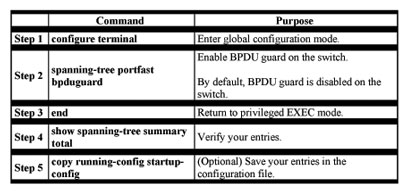
In a valid configuration, Port Fast-enabled interfaces do not receive BPDUs. Receiving a BPDU on a Port Fast-enabled interface means an invalid configuration, such as the connection of an unauthorized device. If a BPDU is received on Port Fast-enabled interface, the BPDU guard feature places the interface into the ErrDisable state. The BPDU guard feature provides a secure response to invalid configurations because you must manually put the interface back in service.
To disable BPDU guard, use the no spanning-tree portfast bpduguard global configuration command.
Configuring UplinkFast for Use with Redundant Links
UplinkFast increases the switch priority to 49152 and adds 3000 to the STP path cost only if the port used the default path cost before UplinkFast was enabled, making it unlikely that the switch will become the root switch. The max-update-rate represents the number of multicast packets transmitted per second (the default is 150 packets per second). UplinkFast cannot be enabled on VLANs that have been configured for switch priority. To enable UplinkFast on a VLAN with switch priority configured, first restore the switch priority on the VLAN to the default value by using a no spanning-tree vlan vlan-id priority global configuration command.
Note When you enable UplinkFast, it affects all VLANs on the switch. You cannot configure UplinkFast on an individual VLAN.
Beginning in privileged EXEC mode, follow these steps to enable UplinkFast:
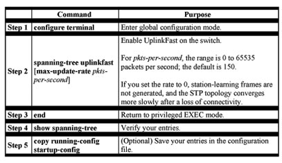
When UplinkFast is enabled, the switch priority of all VLANs is set to 49152, and the path cost of all interfaces and VLAN trunks is increased by 3000 if you did not modify the path cost from its default setting. This change reduces the chance that the switch will become the root port. When UplinkFast is disabled, the switch priorities of all VLANs and path costs of all interfaces are set to default values if you did not modify them from their defaults.
To return the update packet rate to the default setting, use the no spanning-tree uplinkfast max-update-rate global configuration command. To disable UplinkFast, use the no spanning-tree uplinkfast command.
Configuring Cross-Stack UplinkFast
Before enabling CSUF, make sure your stack switches are properly connected.
Beginning in privileged EXEC mode, follow these steps to enable CSUF:
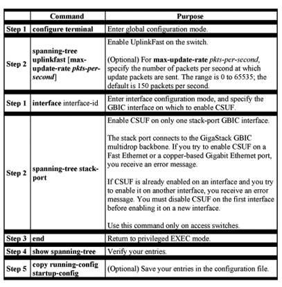
To disable CSUF on an interface, use the no spanning-tree stack-port interface configuration command. To disable UplinkFast on the switch and all of its VLANs, use the no spanning-tree uplinkfast global configuration command.
Configuring BackboneFast
You can enable BackboneFast to detect indirect link failures and to start the spanningtree reconfiguration sooner.
Note If you use BackboneFast, you must enable it on all switches in the network. BackboneFast is not supported on Token Ring VLANs. This feature is supported for use with third-party switches.
Beginning in privileged EXEC mode, follow these steps to enable BackboneFast:
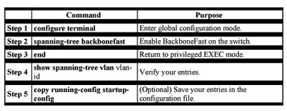
To disable the BackboneFast feature, use the no spanning-tree backbonefast global configuration command.
Configuring Root Guard
Root guard enabled on an interface applies to all the VLANs to which the interface belongs. Each VLAN has its own spannning-tree instances.
Do not enable the root guard on interfaces to be used by the UplinkFast feature. With UplinkFast, the backup interfaces (in the blocked state) replace the root port in the case of a failure. However, if root guard is also enabled, all the backup interfaces used by the UplinkFast feature are placed in the root-inconsistent state (blocked) and are prevented from reaching the forwarding state.
Beginning in privileged EXEC mode, follow these steps to enable root guard on an interface:
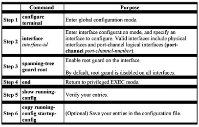
To disable the root guard feature, use the no spanning-tree guard or the spanning-tree guard none interface configuration commands.
I hope you found this article to be of use and it helps you prepare for your Cisco CCNA certification. Achieving your CCNA certification is much more than just memorizing Cisco exam material. It is having the real world knowledge to configure your Cisco equipment and be able to methodically troubleshoot Cisco issues. So I encourage you to continue in your studies for your CCNA exam certification.